Brand sort
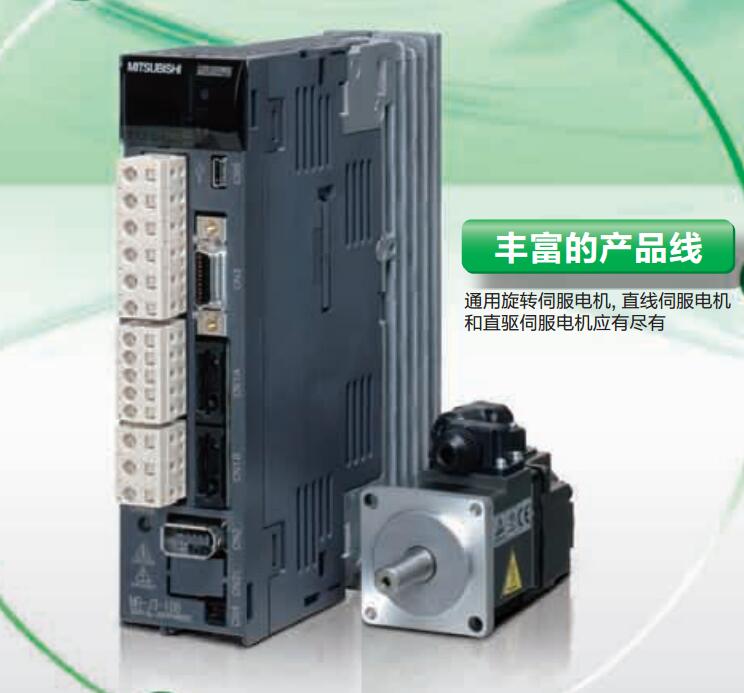
MITSUBISHI MITSUBISHI HF-JP103B Price
Brand:
MITSUBISHI
Country: JAPAN
Name: Low inertia medium / high power servo motor
Model: HF-JP103B
Price: 0
MITSUBISHI HF-JP103B
Capacity: 1MB.Input and output points: 20 points.
Power supply: AC100-240V.
Input points: 12 points.
Output points: 8 points.
Output form: transistor output (drain).
Power consumption: 20W.
Weight: 0.4KG.
Outline dimension: 75x90x75mm.
A new application model.
FX3SA is a basic model on the basis of the basic performance of FX1S above the expansion of the expansion of the new model.
FX3SA is applicable to all kinds of fields of small scale equipment which need to simulate the quantity and function of MODBUS and Ethernet HF-JP103B
Basic models suitable for small scale control.
Compact but powerful,
At the same time, the analog quantity and communication function, etc.. Motor series: ultra low inertia, small capacity.
Using a serial absolute / incremental encoder.
Rated output power: 0.05kw.
Rated speed: 3000rpm.
With the brake with brake.
Without GB.
Shaft end: straight shaft.
The rotor of the servo motor is a permanent magnet, and the control of the servo amplifier is controlled by the U/V/W three-phase electric electromagnetic field,
The rotor rotates under the action of the magnetic field, and the encoder feedback signal of the motor is given to the driver,
According to the feedback value and the target value, the driver is compared,
Adjust the rotor rotation angle.
The accuracy of the servo motor is determined by the resolution of the encoder. Drive: MR-H_ACN series CC-LINK features.
Rated output: 0.2KW.
The test system is composed of two parts, namely, the servo driver, the motor system and the host computer.
The host computer sends the speed command signal to the servo driver,
Servo drives start to run in accordance with the instructions.
In the course of operation, the running data of the servo system is collected by the host computer and the data acquisition circuit,
And carries on the preservation, the analysis and the display to the data. Because the motor is not loaded in this test system,
So compared with the previous two kinds of testing systems, the system has a relatively small volume,
And the measurement and control circuit of the system is relatively simple,
But it also makes the system can not simulate the actual operation of the servo drive.
Usually, such testing system is only used to test the rotational speed and angular displacement of the tested system under no-load condition,
And can not carry on the comprehensive and accurate test to the servo drive.
HF-JP103B Operation manual / Instructions / Catalog download link: /searchDownload.html?Search=HF-JP103B&select=5
...more relevant model market price >>>>
Related products
MITSUBISHI
Low inertia medium / high power servo motor
HF-JP5034B
Servo motor series: low inertia, medium
MITSUBISHI
Low inertia medium / high power servo motor
HF-JP103
Servo motor series: low inertia, medium
MITSUBISHI
Low inertia medium / high power servo motor
HF-JP7034
Servo motor series: low inertia, medium
MITSUBISHI
Low inertia medium / high power servo motor
HF-JP153
Servo motor series: low inertia, medium
Related download


 next one:
  Last one: