Brand sort
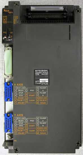
MITSUBISHI MITSUBISHI A0J2D71 Price
MITSUBISHI A0J2D71
TFT color LCD touch screen to replace the backlight.
Applicable models: A975/970GOT-TB_-B, A975/970GOT-TBA, A975/970GOT-TBD. Cable length: 50m.
For MR-J2S-700A (4) /CP/CL or less.
Encoder for HC-SFS; HC-LFS; HC-RFS; 2000r/min HA-LFS; HC-UFS servo motor.
-H products have a long flex life.
Coding is not resistant to oil.
A7HGP/A6GPP-CPU connection.
Length: 30m. Max input / output points: 20 points.
Power supply voltage: 24VDC A0J2D71
Input points: 12 points.
Output points: 8 points.
Output type: relay.
Power consumption (W): 7.
Weight (kg):0.3.
Size (WxHxD) mm:75x90x49.
Host has 10 points (6I/4O), 14 points (8I/6O), 20 points (12I/8O), 30 points (16I/14O) of 4 types.
This type of PLC is mainly used in all of the digital input, digital output control point of the device.
Can be directly connected to the 220V city power, built-in 8K step EEPROM memory, no battery, easy to maintain.
The series transistor output (MT) of the PLC, can be output 2 100KHz pulse, direct drive servo or stepper motor.
The series PLC can not be brought with the expansion module, but can be installed by the BD board to extend a small amount of I/O.
The series 1N through the installation of BD series PLC board, can achieve RS232, RS485, RS422 communication.
All equipment is digital input and output point.
The total I/O points are not more than 30 points, and the input points are less than 16, the output points are less than 14.
Its MT series of PLC can drive 2 way servo or stepper, commonly used in the control system for a simple manipulator. Length: 0.1m.GI fiber optic cable.
Dual loop for Q mode.
Remote I/O network (remote control station).
How to choose MITSUBISHI PLC.
MITSUBISHI PLC options include the choice of MITSUBISHI PLC models, capacity, I/O module, power, etc..
MITSUBISHI PLC distribution I/O points and design MITSUBISHI PLC peripheral hardware circuit
Draw the I/O point of the PLC and the input / output device connection diagram or the corresponding table,
This part also can be carried out in second steps.
Design PLC peripheral hardware circuit.
Draw the electrical wiring diagram of the other parts of the system,
Including the main circuit and the control circuit does not enter the PLC, etc..
The electrical schematic diagram of the system composed of I/O PLC connection diagram and PLC peripheral electrical circuit diagram.
So far the system''s hardware electrical circuit has been determined.
A0J2D71 Operation manual / Instructions / Catalog download link: /searchDownload.html?Search=A0J2D71&select=5
...more relevant model market price >>>>
Related products
MITSUBISHI
Analog input module
A0J2-68AD
8 channels.
Input: DC-10 10V, DC4 20
MITSUBISHI
CPU unit
A0J2CPUP23
Input and output points: 480 points.
Pro
MITSUBISHI
DC input / relay output module
A0J2-E56DR
Input points: 32 points.
Input voltage a
MITSUBISHI
Connecting cable
A0J2-C03
Horizontally placed cale.
Length: 300mm
Related download


 next one:
  Last one: