Brand sort
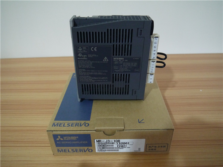
MITSUBISHI MITSUBISHI MR-J3-10B Price
Brand:
MITSUBISHI
Country: JAPAN
Name: SSCNET type III optical fiber communication driver
Model: MR-J3-10B
Market price: U.S.$ 867.8
(The following are the market open price not sales price!)
(The following are the market open price not sales price!)
MITSUBISHI MR-J3-10B
Redundant CPU data tracking cable length of 3 meters.
Can only be used for MITSUBISHI Q series PLC redundancy CPU.Servo motor series: low inertia, medium / high power.
Rated output: 12.0kw.
Rated speed: 1000r/min.
Electromagnetic brake: No.
Shaft end specification: Standard (straight axis).
Voltage: 400V level.
Features: low inertia has low medium and high speed three models, suitable for different applications as a standard, 30KW and above servo motor can be installed flange or bracket MR-J3-10B
IP level: IP44.
Application example:
1, injection molding machine.
2, semiconductor manufacturing equipment.
3, large material handling system.
4, stamping machine.
Abundant motor product line can optimize the performance of the machine.
Has a rich motor product line including a rotary servo motor, linear servo motor and direct drive motor. For video input (NTCS/PAL) 4 channel / RGB input 1 channel composite input.
Applicable model: GT15. Position detection axis number: 1 axis.
Resolution: 4096 * 32 * 409.6 * 320.
Number of output channels: 16 channels.
When communicating in the PLC network of MITSUBISHI,
There is no sense of difference and discontinuity in the network,
Can carry on the remote monitoring, modification, debugging and other work of data communication and program,
Without taking into account the level and type of network.
MELSECNET/H and CC-Link use the way of loop communication,
Periodically automatically send and receive messages,
Does not require specialized data communication procedures,
Simple parameters can be set.
MELSECNET/H and CC-Link are used to transmit and receive the broadcast mode,
This can be done on the network data sharing.
For the use of Ethernet, MELSECNET/H, CC-Link network,
Can set the network parameters and various functions, simple and convenient in the Developer GX software screen. Input and output points: 512 points.
Input / output data points: 8192 points.
Program capacity: 28k.
Basic command processing speed (LD command) S:0.075.
PLC in the program execution stage: according to the order of the user program order to store the order of each instruction,
After the corresponding operation and processing, the result is written to the output status register,
The contents of the output status register are changed with the execution of the program.
Output refresh phase: when all instructions are executed,
The output status register is sent to the output latch in the output refresh stage,
And through a certain way (relay, transistor or transistor) output, drive the corresponding output equipment.
MR-J3-10B Operation manual / Instructions / Catalog download link: /searchDownload.html?Search=MR-J3-10B&select=5
...more relevant model market price >>>>
Related products
MITSUBISHI
Servo driver
MR-J4-60A-RJ
1 axis servo amplifier.
MITSUBISHI gener
MITSUBISHI
CC-Link communication driver
MR-J3-22KT4
MITSUBISHI motor universal AC servo ampl
MITSUBISHI
Universal interface servo amplifier
MR-J2S-22KA
MITSUBISHI general purpose AC servo ampl
MITSUBISHI
Servo driver
MR-J200A
Type: MR-J series.
Rated output: 2.0KW.
Related download


 next one:
  Last one: