Brand sort
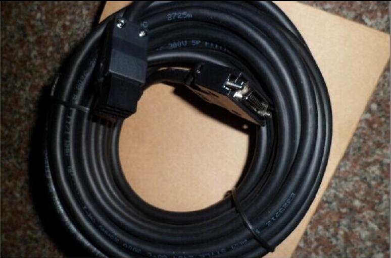
MITSUBISHI MITSUBISHI MR-PWCNS4 Price
Brand:
MITSUBISHI
Country: JAPAN
Name: Connector kit for motor power supply
Model: MR-PWCNS4
Market price: U.S.$ 111.86
(The following are the market open price not sales price!)
(The following are the market open price not sales price!)
MITSUBISHI MR-PWCNS4
Master / local station.
AnCPU use.
According to the control requirements of the system, using the appropriate design method to design MITSUBISHI PLC program.
Procedures to meet the requirements of system control as the main line,
Write one by one to achieve the control function or the sub task of the program,
Gradually improve the functions specified by the system.
MITSUBISHI PLC initialization procedure MR-PWCNS4 After MITSUBISHI PLC on power, the general need to do some of the initial operation,
In order to start making necessary preparations, to avoid the wrong operation of the system.
The main contents of the initialization program are: to some data area, counter and so on,
Data needed to restore some of the data area,
Set or reset some relays,
For some initial state display, etc.. "Max input / output points: 14 points.
Power supply voltage: DC24V.
Input points: 8 points.
Output points: 6 points.
Output type: Transistor (source).
Power consumption (W): 19.
Weight (kg):0.3.
Size (WxHxD) mm:60x90x75.
Positioning and pulse output functions: a PLC cell can output 2 point 100KHz pulses at the same time.
PLC is equipped with 7 special positioning instructions,
Including zero return, absolute or relative address expression and special pulse output control.
Host has 10 points (6I/4O), 14 points (8I/6O), 20 points (12I/8O), 30 points (16I/14O) of 4 types.
This type of PLC is mainly used in all of the digital input, digital output control point of the device.
Can be directly connected to the 220V city power, built-in 8K step EEPROM memory, no battery, easy to maintain.
The series transistor output (MT) of the PLC, can be output 2 100KHz pulse, direct drive servo or stepper motor.
The series PLC can not be brought with the expansion module, but can be installed by the BD board to extend a small amount of I/O.
The series 1N through the installation of BD series PLC board, can achieve RS232, RS485, RS422 communication. "Power: 30kw.
Voltage: 400V.
Brake resistor, a kind of ripple resistance, is mainly used in the mechanical system of the inverter to control the speed of the motor,
Help the motor to be converted into heat energy due to the regenerative power of the motor.
Braking unit principle: the brake unit is composed of a high power transistor GTR and its driving circuit.
Its function is to link the discharge current braking resistor capacitor voltage or not in the range of the time consumed and the DC part "overpressure",
Need to add external braking components, in order to speed up the speed of the consumption of renewable energy. "
MR-PWCNS4 Operation manual / Instructions / Catalog download link: /searchDownload.html?Search=MR-PWCNS4&select=5
...more relevant model market price >>>>
Related products
MITSUBISHI
Power connector
MR-PWCNK1
A power supply connector set for HC-KFS
MITSUBISHI
Power connector
MR-PWCNK2
A power supply connector set for HC-KFS
MITSUBISHI
Connector kit for motor power supply
MR-PWCNS4
Motor power adapter kit HF-SP51 81 10
MITSUBISHI
Cable for power supply of servo motor
MR-PWS2CBL03M-A1-L
The length of the line: 2M.
IP level: IP
Related download


 next one:
  Last one: