
Home
>> Products
>> MITSUBISHI
>> Ans/QnAs series PLC
>> Computer communication module
>> A1SJ71C24-R2 Computer link module
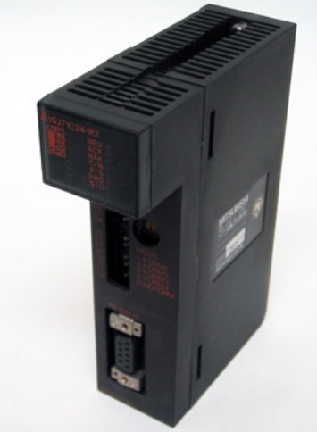
A1SJ71C24-R2 Computer link module
MITSUBISHI A1SJ71C24-R2 Manual And Instructions
A1SJ71C24-R2 datasheetPDF datasheet
A1SJ71C24-R2 User's Manual
A1SJ71C24-R2 HardwareUser's Manual
MITSUBISHI A1SJ71C24-R2 Product information and technical parameters:
Brand: MITSUBISHI
Name: Computer link module
Model: A1SJ71C24-R2
...More relevant models >>>>
A1SJ71C24-R2 datasheetPDF datasheet
A1SJ71C24-R2 User's Manual
A1SJ71C24-R2 HardwareUser's Manual
MITSUBISHI A1SJ71C24-R2 Product information and technical parameters:
Brand: MITSUBISHI
Name: Computer link module
Model: A1SJ71C24-R2
Axis of control: 1.
A1SD75 series components show the MITSUBISHI in the manufacture and design of CNC, frequency converter,
Integrated technical experience in servo system and PLC.
These components have a wealth of features that are sufficient to meet the highest requirements in the application of positioning control A1SJ71C24-R2.
Up to 3 axis linkage operation,
In low cost motion control applications, this component can be used to control the operation of a multi - to 3 axis, which can be used to account for only one slot A1SJ71C24-R2 RS-232 1 channel.
RS-422/485 1 channel.
Transmission speed: 2 channels.
At the same time the use of 115.2kbps may.
When the programmer input programinto the user program memory,
Then CPU according to the function of the system (the system program memory to explain the compiler),
Translate the user program into PLC internally recognized by the user to compile the program A1SJ71C24-R2.
Input status and input information input from the input interface,
CPU will be stored in the working data memory or in the input image register.
And then combine the data and the program with CPU.
The result is stored in the output image register or the working data memory,
And then output to the output interface, control the external drive A1SJ71C24-R2.
Semiconductor circuit with memory function.
System program memory and user memory.
System program memory for storing system program,
Including management procedures, monitoring procedures, as well as the user program to do the compiler to compile the process of interpretation.
Read only memory. Manufacturers use, content can not be changed, power does not disappear.
User memory: user program storage area and work data storage area.
Composed of random access memory (RAM). User use.
Power cut off. Commonly used efficient lithium battery as a backup power supply, life is generally 3~5 years. Enter 64 points.
Above DC7V.
Response time: 16ms.
16 pin connector.
Output 64 points.
Response time: 16ms.
32 pin connector dynamic input and output data.
PLC is introduced by the relay control technology after the development of micro processing technology,
Can be easily and reliably used for switching control.
As the analog quantity can be converted into digital quantity, the number of digital quantity is just a number of switching value,
Therefore, after the conversion of analog, PLC can also be reliable for processing control.
Because the continuous production process often has the analog quantity, the analog quantity control is sometimes called process control.
Analog quantity is not electricity, and PLC can only handle digital quantity, quantity of electricity.
All to realize the conversion between them to have the sensor, the analog quantity into a number of power.
If this power is not standard, but also through the transmitter,
The non-standard power into a standard electrical signal, such as 1-5V, 4-20mA, 0-10V, etc..
At the same time, there is also an analog input unit (A/D),
Transform these standard elecctrical signals into digital signals,
The analog output unit (D/A), in order to transform the digital quantity after PLC processing into analog quantity -- standard electric signal A1SJ71C24-R2.
So the standard telecommunication number, the conversiion between the number of operations to use a variety of computing A1SJ71C24-R2.
This requires the resolution of the analog unit and the standard electrical signal.
...More relevant models >>>>
 Last one: MITSUBISHI Computer link module A1SJ71C24-PRF
 next one: MITSUBISHI Computer link module A1SJ71C24-R4
Related download