
Home
>> Products
>> MITSUBISHI
>> Ans/QnAs series PLC
>> Other function modules
>> A1ST60 Analog timer module
A1ST60 Analog timer module
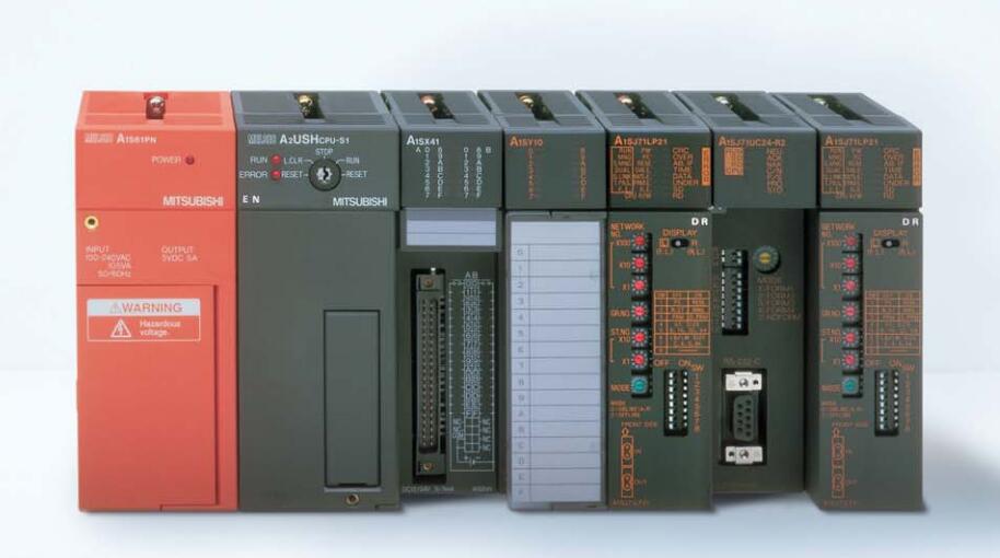
MITSUBISHI A1ST60 Manual And Instructions
A1ST60 datasheetPDF datasheet
A1ST60 HardwareUser's Manual
MITSUBISHI A1ST60 Product information and technical parameters:
Brand: MITSUBISHI
Name: Analog timer module
Model: A1ST60
A1ST60 analog timer module has 8 analog timers.
Each timer can be set between 0.1-600S,
Its accuracy plus or minus 2%.
Dial setting on the timing constant panel of the timer,
With a small screwdriver can be easily adjusted.
...More relevant models >>>>
A1ST60 datasheetPDF datasheet
A1ST60 HardwareUser's Manual
MITSUBISHI A1ST60 Product information and technical parameters:
Brand: MITSUBISHI
Name: Analog timer module
Model: A1ST60
A1ST60 analog timer module has 8 analog timers.
Each timer can be set between 0.1-600S,
Its accuracy plus or minus 2%.
Dial setting on the timing constant panel of the timer,
With a small screwdriver can be easily adjusted.
Type of input: DC leakage.
Input points: 32 points.
Input voltage: DC24.
Input current: 7mA.
Connection mode: terminal row.
Common common point: 32.
Functional block diagram language is a kind of PLC programming language, which is similar to digital logic circuit.
The function module is used to represent the function of the module,
Different function modules have different functions A1ST60.
Functional module figure programming language features: functional block diagram programming language is characterized by a functional module for the unit,
Analysis and understanding of the control scheme is simple and easy: function module is to use graphical form of expression,
Intuitive, for a digital logic circuit based on the design of the staff is very easy to master the programming;
Control system with complex scale and complex control logic,
Because the function module diagram can clearly express the function relation, the programming debugging time is greatly reduced A1ST60 A1ST60 8 slots; requires 1 AnS series PLC power modules;
Used to install large AnS series PLC module.
Base plate of AnS series PLC.
QA1S series PLC 8 slot main substrate A1ST60.
AnS series of modules can be installed. Input and output points: 512 points.
Input / output data points: 8192 points.
Program capacity: 28k.
Basic command processing speed (LD command) S:0.2.
PLC in the program execution stage: according to the order of the user program order to store the order of each instruction,
After the corresponding operation and processing, the result is written to the output status register,
The contents of the output status register are changed with the execution of the program.
Output refresh phase: when all instructions are executed,
The ouutput status register is sent to the output latch in the output refresh stage,
And through a certain way (relay, transistor or transistor) output, drive the corresponding output equipment A1ST60. 8 slots; requires 1 AnS series PLC power modules;
Useed to install large AnS series PLC module A1ST60.
Base plate of AnS series PLC.
QA1S series PLC 8 slot main substrate.
AnS series of modules can be installed.
...More relevant models >>>>
 Last one: MITSUBISHI Pulse capture module A1SP60
 next one: MITSUBISHI Intelligent communication module A1SD51S
Related download