
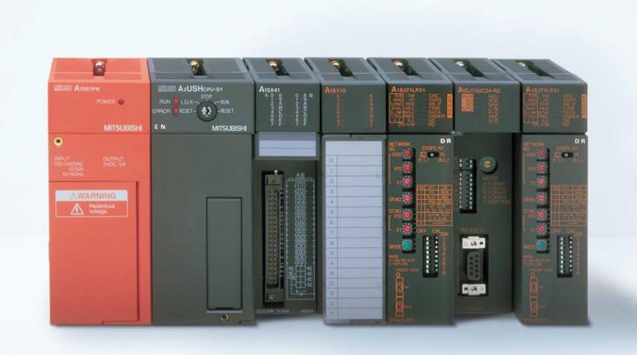
A1SY68A output module
MITSUBISHI A1SY68A Manual And Instructions
A1SY68A datasheetPDF datasheet
A1SY68A User's Manual
MITSUBISHI A1SY68A Product information and technical parameters:
Brand: MITSUBISHI
Name: output module
Model: A1SY68A
Output type: transistor source / drain type.
Output points: 8 points.
Load voltage: DC5/12/24/48.
Load current: 2A.
Connection mode: terminal row.
Common public end points: 1.
Switching value, also known as logic, refers to only two values, 0 or 1, ON or OFF.
It is the most common control, it is the advantage of PLC control,
Is also the most basic application of PLC.
Switch volume control is designed to,
According to the current input combination of the switch quantity and the history of the input sequence,
So that PLC generates the corresponding switching output,
In order to make the system work in a certain order.
So, sometimes also known as the order control.
And sequential control is divided into manual, semi-automatic or automatic.
And the control principle is decentralized, centralized and hybrid control three.
...More relevant models >>>>
A1SY68A datasheetPDF datasheet
A1SY68A User's Manual
MITSUBISHI A1SY68A Product information and technical parameters:
Brand: MITSUBISHI
Name: output module
Model: A1SY68A
Output type: transistor source / drain type.
Output points: 8 points.
Load voltage: DC5/12/24/48.
Load current: 2A.
Connection mode: terminal row.
Common public end points: 1.
Switching value, also known as logic, refers to only two values, 0 or 1, ON or OFF.
It is the most common control, it is the advantage of PLC control,
Is also the most basic application of PLC.
Switch volume control is designed to,
According to the current input combination of the switch quantity and the history of the input sequence,
So that PLC generates the corresponding switching output,
In order to make the system work in a certain order.
So, sometimes also known as the order control.
And sequential control is divided into manual, semi-automatic or automatic.
And the control principle is decentralized, centralized and hybrid control three.
Available network: 10BASE2.
Max / total distance: 185/925m.
A1SJ71E71 is a compact Ethernet interface module,
Used to hang PLC series ANS to ethernet.
There are two kinds of hanging network modules: A1SJ71E71-B2-S3 and A1SJ71E71-B5-S3 respectively corresponding to 10BASE2 and 10BASE5,
So that the vast majority of installed cable can continue to use A1SY68A. 2 channels.
200/10kpps.
Count input signal: DC5/12/24V A1SY68A
External input: DC5/12/24V.
Compare output: transistor DC12/24V, 0.5A/1 point, 2A/1 common.
20 point terminal station.
Structured text language is a programming language that describes a program with a structured description of the text.
It is a programming language similar to a high level language A1SY68A. In large and medium
Structured text is often used to describe the relationship between the various variables in the control system based on the PLC system.
Mainly used for other programming languages more difficult to achieve the user program.
Sequential function flow chart language is designed to satisfy the sequential logic control.
The process of sequential process action is divided into steps and transformation conditions,
According to the transfer condition, the control system is distributed in the function flow sequence,
Step by step according to the sequence of actions A1SY68A.
Each step represents a control function, represented by the box.
In the box, the ladder logic is used to complete the task of the corresponding control function.
This programming language makes the program structure clear and easy to read and maintain,
Greatly reduce the programming workload, shorten the programming and debugging time.
Used in the system of the size of the school, procedures for more complex occasions.
Sequence function flow chart programming language features: to function as the main line, in accordance with the functiional flow of the order of distribution, clear, easy to understand the user program,
Avoid the defect of ladder diagram or other languages,
At the same time, the use of ladder language to avoid the use of ladder programming,
Due to the compllicated mechanical interlock, the structure of the user program is complex and difficult to understand,
User program scan time is also greatly reduced A1SY68A A1SY68A.
...More relevant models >>>>
 Last one: MITSUBISHI Transistor source type output module A1SY60E
 next one: MITSUBISHI output module A1SY71
Related download