
Home
>> Products
>> MITSUBISHI
>> A/QnA series PLC
>> High function module
>> Other high function modules
>> A3VTU Multiple system module
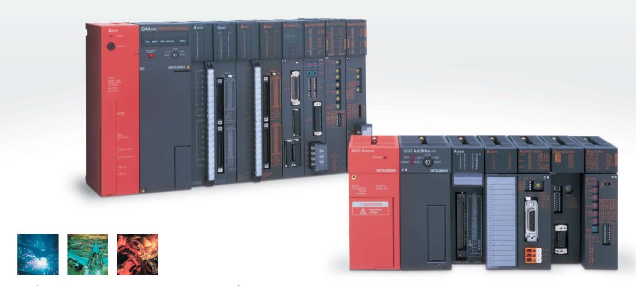
A3VTU Multiple system module
MITSUBISHI A3VTU Manual And Instructions
A3VTU datasheetPDF datasheet
MITSUBISHI A3VTU Product information and technical parameters:
Brand: MITSUBISHI
Name: Multiple system module
Model: A3VTU
Module for A3VTS multiplex system.
MITSUBISHI PLC detection, fault diagnosis and display and other procedures.
These procedures are relatively independent, generally in the basic completion of the program design and then add.
MITSUBISHI PLC protection and chain procedures.
Protection and chain is an indispensable part of the program, must be carefully considered.
It can avoid the control logic confusion caused by illegal operations.
...More relevant models >>>>
A3VTU datasheetPDF datasheet
MITSUBISHI A3VTU Product information and technical parameters:
Brand: MITSUBISHI
Name: Multiple system module
Model: A3VTU
Module for A3VTS multiplex system.
MITSUBISHI PLC detection, fault diagnosis and display and other procedures.
These procedures are relatively independent, generally in the basic completion of the program design and then add.
MITSUBISHI PLC protection and chain procedures.
Protection and chain is an indispensable part of the program, must be carefully considered.
It can avoid the control logic confusion caused by illegal operations.
Input voltage range: AC100 ~ 120V/AC200 ~ 240V.
Output voltage: DC5/12V.
Output current: 2.3A/1.5A.
I/O points is an important indicator of PLC.
Reasonable selection of I/O points can not only satisfy the control requirements of the system,
And the total investment of the system is the lowest.
The input and output points and types of PLC should be determined according to the analog quantity and switch quantity of the controlled object,
Generally an input / output element to take up an input / output point A3VTU A3VTU
Taking into account the future adjustment and expansion,
In general should be estimated on the total number of points plus the amount of spare 20%~30%.
The following describes the centralized control system I/O points of the estimate A3VTU.
Relay output interface circuit of PLC
Working process: when the internal circuit output digital signal 1,
There is a current flowing through, the relay coil has a current, and then the normally open contact is closed,
Provide load current and voltage.
When the internal circuit outputs a digital signal 0, there is no current flowing through it,
The relay coil does not have a current, and the normally open contact is broken off,
A current or voltage that is disconnected from the load A3VTU.
It is through the output interface circuit to the internal digital circuit into a signal to make the load action or not action. RS-232 2 channel.
Transfer speed: 0.3-19.2kbps.
Equipment layer / field bus CC-Link device layer is the PLC and other control devices and sensors and drive devices connected to the field network,
Network for the lowest layer of the whole network system.
Using CC-Link field bus connection, the number of wiring is greatly reduced,
Improve the maintainability of the system.
And, not just the amount of data ON/OFF and other switches,
Can also be connected to the ID system, bar code reader, inverter, man-machine interface and other intelligent devices,
From the completion of a variety of data communication, the management of the terminal production information can be realized,
On the centralized management of the state oof the machine movement,
Make maintenance work efficiency also greatly improved A3VTU A3VTU.
Q series PLC in the use of CC-Link function better,
And easier to use.
...More relevant models >>>>
 Last one:
  next one:
 Related download