
Home
>> Products
>> MITSUBISHI
>> A/QnA series PLC
>> Input module / output module
>> Input module
>> A70LX-S3 Input module
A70LX-S3 Input module
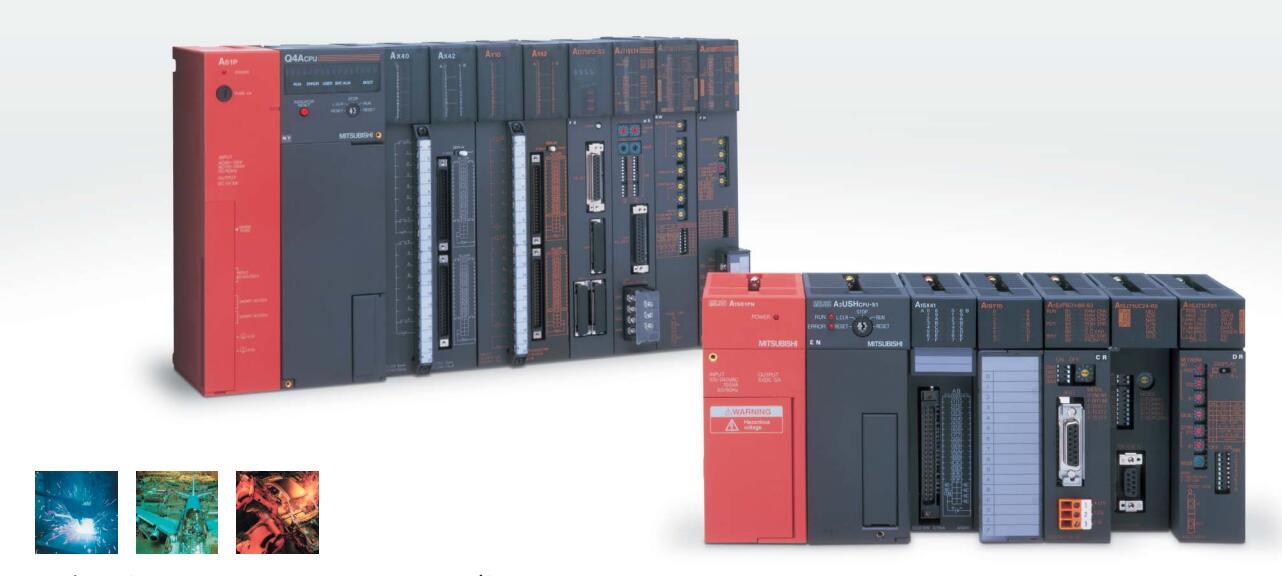
MITSUBISHI A70LX-S3 Manual And Instructions
A70LX-S3 datasheetPDF datasheet
MITSUBISHI A70LX-S3 Product information and technical parameters:
Brand: MITSUBISHI
Name: Input module
Model: A70LX-S3
Input unit (upper / lower limit LS signal) (NSD servo system)
Each scanning process. Focus on the input signal sampling. Focus on the output signal to refresh.
Input refresh process. When the input port is closed,
Program in the implementation phase, the input end of a new state, the new state can not be read.
Only when the program is scanned, the new state is read.
A scan cycle is divided into the input sample, the program execution, the output refresh.
The contents of the component image register are changed with the change of the execution of the program.
The length of the scan cycle is determined by the three.
CPU the speed of executing instructions.
Time of instruction.
Instruction count.
Due to the adoption of centralized sampling.
Centralized output mode.
There exist input / output hysteresis phenomena, i.e., the input / output response delay.
PLC selection with the development of PLC technology, more and more types of PLC products,
Function is becoming more and more perfect, and its application is more and more extensive.
Different series of different models of PLC has different performance, applicable occasions also have different emphasis,
Price also has a greater difference. Therefore PLC selection,
Under the premise of meeting the control requirements,
Should consider the best performance to price ratio, a reasonable choice of PLC.
System program memory for storing system program,
Including management procedures, monitoring procedures, as well as the user program to do the compiler to compile the process of interpretation.
Read only memory. Manufacturers use, content can not be changed, power does not disappear.
...More relevant models >>>>
A70LX-S3 datasheetPDF datasheet
MITSUBISHI A70LX-S3 Product information and technical parameters:
Brand: MITSUBISHI
Name: Input module
Model: A70LX-S3
Input unit (upper / lower limit LS signal) (NSD servo system)
Each scanning process. Focus on the input signal sampling. Focus on the output signal to refresh.
Input refresh process. When the input port is closed,
Program in the implementation phase, the input end of a new state, the new state can not be read.
Only when the program is scanned, the new state is read.
A scan cycle is divided into the input sample, the program execution, the output refresh.
The contents of the component image register are changed with the change of the execution of the program.
The length of the scan cycle is determined by the three.
CPU the speed of executing instructions.
Time of instruction.
Instruction count.
Due to the adoption of centralized sampling.
Centralized output mode.
There exist input / output hysteresis phenomena, i.e., the input / output response delay.
PLC selection with the development of PLC technology, more and more types of PLC products,
Function is becoming more and more perfect, and its application is more and more extensive.
Different series of different models of PLC has different performance, applicable occasions also have different emphasis,
Price also has a greater difference. Therefore PLC selection,
Under the premise of meeting the control requirements,
Should consider the best performance to price ratio, a reasonable choice of PLC.
System program memory for storing system program,
Including management procedures, monitoring procedures, as well as the user program to do the compiler to compile the process of interpretation.
Read only memory. Manufacturers use, content can not be changed, power does not disappear.
Bus connection.
Program 2 channel connection.
MITSUBISHI PLC detection, fault diagnosis and display and other procedures.
These procedures are relatively independent, generally in the basic completion of the program design and then add.
MITSUBISHI PLC protection and chain procedures.
Protection and chain is an indispensable part of the program, must be carefully considered A70LX-S3.
It can avoid the control logic confusion caused by illegal operations A70LX-S3 CPU connection program input device.
ACPU use. Ethernet network module 10BASE-T/10BASE5.
Control layer /MELSECNET/10 (H) is the middle layer of the whole network system,
Control network which is convenient and high speed processing data transmission between PLC, CNC and other control equipment A70LX-S3.
As MELSEC control network MELSECNET/10,
With its good real-time performance, simple network settings, no procedures of the network data sharing concept,
As well as the redundant circuit and so on, has obtained the very high market appraisal,
The number of devices to reach the highest in japan,
In the world is also one of the few.
And MELSECNET/H not only inherited the excellent characteristics of MELSECNET/10,
Also makes the network real-time better, more data capacity,
Further adapt to the needs of the market A70LX-S3. RS-232:1, RS-422/485:1.
Transmission speed: 0.3 ~ 19.2kpbs.
Computer connection function.
A3VCPU special.
Printer / peripheral device connection, BASIC language function.
How to choose MITSUBISHI PLC.
MITSUBISHI PLC options include the choice of MITSUBISHI PLC models, capacity, I/O module, power, etc..
MITSUBISHI PLC distribution I/O points and design MITSUBISHI PLC peripheral hardware circuit
Draw the I/O point of the PLC and the input / output device connection diagram or the corresponding table,
This part also can be carried out in second steps.
Dessign PLC peripheral hardware circuit A70LX-S3.
Draw the electrical wiring diagram of the other parts of the system,
Including the main circuit and the control circuit does not enter the PLC, etc..
The electrical schematic diagram of the system compoosed of I/O PLC connection diagram and PLC peripheral electrical circuit diagram A70LX-S3.
So far the system''s hardware electrical circuit has been determined.
...More relevant models >>>>
 Last one:
  next one:
 Related download
Related model