
Home
>> Products
>> MITSUBISHI
>> A/QnA series PLC
>> High function module
>> MELSECNET module
>> AJ71AR21 Network module
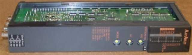
AJ71AR21 Network module
MITSUBISHI AJ71AR21 Manual And Instructions
AJ71AR21 datasheetPDF datasheet
AJ71AR21 User's Manual
MITSUBISHI AJ71AR21 Product information and technical parameters:
Brand: MITSUBISHI
Name: Network module
Model: AJ71AR21
3C-2V/5C-2V coaxial cable.
Double circuit.
MELSECNET (II) (Master / local station).
According to the control requirements of the system, using the appropriate design method to design MITSUBISHI PLC program.
Procedures to meet the requirements of system control as the main line,
Write one by one to achieve the control function or the sub task of the program,
Gradually improve the functions specified by the system.
MITSUBISHI PLC initialization procedure. After MITSUBISHI PLC on power, the general need to do some of the initial operation,
In order to start making necessary preparations, to avoid the wrong operation of the system.
The main contents of the initialization program are: to some data area, counter and so on,
Data needed to restore some of the data area,
Set or reset some relays,
For some initial state display, etc..
...More relevant models >>>>
AJ71AR21 datasheetPDF datasheet
AJ71AR21 User's Manual
MITSUBISHI AJ71AR21 Product information and technical parameters:
Brand: MITSUBISHI
Name: Network module
Model: AJ71AR21
3C-2V/5C-2V coaxial cable.
Double circuit.
MELSECNET (II) (Master / local station).
According to the control requirements of the system, using the appropriate design method to design MITSUBISHI PLC program.
Procedures to meet the requirements of system control as the main line,
Write one by one to achieve the control function or the sub task of the program,
Gradually improve the functions specified by the system.
MITSUBISHI PLC initialization procedure. After MITSUBISHI PLC on power, the general need to do some of the initial operation,
In order to start making necessary preparations, to avoid the wrong operation of the system.
The main contents of the initialization program are: to some data area, counter and so on,
Data needed to restore some of the data area,
Set or reset some relays,
For some initial state display, etc..
Program 1 channel connection, AnCPU/QnACPU use.
MITSUBISHI PLC detection, fault diagnosis and display and other procedures.
These procedures are relatively independent, generally in the basic completion of the program design and then add.
MITSUBISHI PLC protection and chain procedures.
Protection and chain is an indispensable part of the program, must be carefully considered AJ71AR21.
It can avoid the control logic confusion caused by illegal operations AJ71AR21 Input and output points: 2048 points.
Input / output data points: 2048 points.
Program capacity: 30K.
Basic command processing speed (LD command): with 1 s coaxial data communication line function.
Each scanning process. Focus on the input signal sampling AJ71AR21. Focus on the output signal to refresh.
Input refresh process. When the input port is closed,
Program in the implementation phase, the input end of a new state, the new state can not be read.
Only when the program is scanned, the new state is read.
A scan cycle is divided into the input sample, the program execution, the output refresh.
The contents of the component image register are changed with the change of the execution of the program AJ71AR21.
The length of the scan cycle is determined by the three.
CPU the speed of executing instructions.
Time of instruction.
Instruction count.
Due to the adoption of centralized sampling.
Centralized output mode.
There exist input / output hysteresis phenomena, i.e., the input / output response delay.
User program storage capacity: it is a measure of how much the user application can store the number of indicators.
Usually in words or K words as units. 16 bit binary number is a word,
Every 1024 words are 1K words. PLC to store instructions and data in words.
General logical operation instructions each account for 1 words. Timer / counter,
Shift instruction accounted for 2 words. Data operation instructions for 2~4. Input voltage range: AC100 ~ 120V.
Output voltage: DC24V.
Output current: 0.6A.
Relay output interface circuit of PLC
Working process: when the internal circuit output digital signal 1,
There is a current flowing through, the relay coil has a current, and then the normally open contact is closed,
Provide load current and voltage.
When the internal circuit outputs a digital signal 0, there is no current flowing through it,
The relay coil does not have a current, and the normally open contact is broken off,
A current or voltage that is disconnected from the load.
It is through the output interface circuit to the internal digital circuit into a signal to make the load action or not action.
I/O points is an important indicator of PLC.
Reasonable selection of I/O points can not only satisfy the control requirements of the system,
And the total investment of the system is the lowest.
The input and output points and types of PLC should be determiined according to the analog quantity and switch quantity of the controlled object,
Generally an input / output element to take up an input / output point AJ71AR21.
Taking into account the future adjustment and expansion,
In general should be estimaated on the total number of points plus the amount of spare 20%~30% AJ71AR21.
The following describes the centralized control system I/O points of the estimate.
...More relevant models >>>>
 Last one:
  next one:
 Related download