
Home
>> Products
>> MITSUBISHI
>> A/QnA series PLC
>> Network / serial communication module
>> AJ71E71 Network module
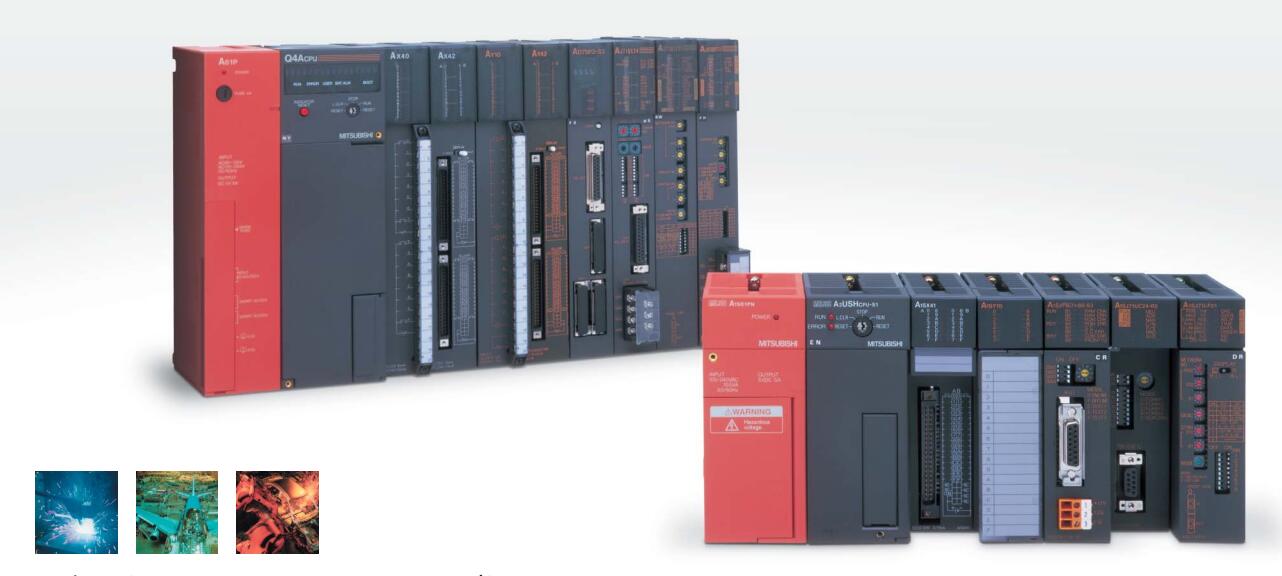
AJ71E71 Network module
MITSUBISHI AJ71E71 Manual And Instructions
AJ71E71 datasheetPDF datasheet
AJ71E71 User's Manual
MITSUBISHI AJ71E71 Product information and technical parameters:
Brand: MITSUBISHI
Name: Network module
Model: AJ71E71
10BASE5/10BASE2
When communicating in the PLC network of MITSUBISHI,
There is no sense of difference and discontinuity in the network,
Can carry on the remote monitoring, modification, debugging and other work of data communication and program,
Without taking into account the level and type of network.
MELSECNET/H and CC-Link use the way of loop communication,
Periodically automatically send and receive messages,
Does not require specialized data communication procedures,
Simple parameters can be set.
MELSECNET/H and CC-Link are used to transmit and receive the broadcast mode,
This can be done on the network data sharing.
For the use of Ethernet, MELSECNET/H, CC-Link network,
Can set the network parameters and various functions, simple and convenient in the Developer GX software screen.
...More relevant models >>>>
AJ71E71 datasheetPDF datasheet
AJ71E71 User's Manual
MITSUBISHI AJ71E71 Product information and technical parameters:
Brand: MITSUBISHI
Name: Network module
Model: AJ71E71
10BASE5/10BASE2
When communicating in the PLC network of MITSUBISHI,
There is no sense of difference and discontinuity in the network,
Can carry on the remote monitoring, modification, debugging and other work of data communication and program,
Without taking into account the level and type of network.
MELSECNET/H and CC-Link use the way of loop communication,
Periodically automatically send and receive messages,
Does not require specialized data communication procedures,
Simple parameters can be set.
MELSECNET/H and CC-Link are used to transmit and receive the broadcast mode,
This can be done on the network data sharing.
For the use of Ethernet, MELSECNET/H, CC-Link network,
Can set the network parameters and various functions, simple and convenient in the Developer GX software screen.
Input and output points: 4096 points.
Input / output data points: 8192 points.
Program capacity: 124k.
Basic command processing speed (LD command) S:0.075.
Multiple CPU (co processor loading).
The length of time required to execute the instruction, the length of the user''s program, the type of instruction, and the speed of the CPU execution are very significant,
Generally, a scanning process, the fault diagnosis time,
Communication time, input sampling and output refresh time is less,
The execution time is accounted for the vast majority of AJ71E71 AJ71E71
The photoelectric coupler is composed of two luminous two extreme tubes and a photoelectric transistor.
Light emitting diode two: the input of a photo coupler and the change of electrical signal,
The light signal is generated by the light emitting diode, which is the same as the input signal AJ71E71.
The working process of the input interface circuit: when the switch is closed, the diode light,
The transistor is then guided to the internal circuit and input signal under the irradiation of the light.
When the switch is off, the diode does not emit light, and the transistor is not on the way AJ71E71. Internal circuit input signal.
It is through the input interface circuit to the external switch signal into PLC internal can accept the digital signal.
Photoelectric three levels: in the light of the light signal conduction, the degree of light signal and the intensity of the light signal.
The output signal has a linear relationship with the input signal in the linear operating region of the photoelectric coupler.
User program storage capacity: it is a measure of how much the user application can store the number of indicators.
Usually in words or K words as units. 16 bit binary number is a word,
Every 1024 words are 1K words. PLC to store instructions and data in words.
General logical operation instructions each account for 1 words. Timer / counter,
Shift instruction accounted for 2 words. Data operation instructions for 2~4.
Three slots in one side.
Power supply unit.
Q4AR duplex system.
Switch volume control is designed to,
According to the current input combination of the switch quantity and the history of the input sequence,
So that PLC generates the corresponding switching output,
In order to make the system work in a certain order.
So, sometimes also known as the order control.
And sequential control is divided into manual, semi-automatic or automatic.
And the control principle is decentralized, centralized and hybrid control three.
Each scanning process. Focus on the input signal sampling. Focus on the output signal to refresh.
Input refresh process. When the input port is closed,
Program in the implementation phase, the input end of a new state, the new state can not be read.
Only when the program is scanned, the new state is read.
A scan cycle is divided into the input sample, the program execution, the output refresh.
The contents of the component image register are changed with the change of the execution of the program.
The length of the scan cycle is determined by the three.
CPU the speed of executing instructions.
Time of instruction.
Instruction count.
Due to the adoption of centralized sampling.
Centralizeed output mode AJ71E71.
There exist input / output hysteresis phenomena, i.e., the input / output response delay.
System program memory for storing system program,
Including management procedures, monitoring procedures, as well as the user program tto do the compiler to compile the process of interpretation AJ71E71.
Read only memory. Manufacturers use, content can not be changed, power does not disappear.
...More relevant models >>>>
 Last one: MITSUBISHI Interface unit of ultrasonic linear meter A64BTL
 next one: MITSUBISHI Network module AJ71E71N3-T
Related download