
Home
>> Products
>> MITSUBISHI
>> A/QnA series PLC
>> Network / serial communication module
>> AJ71QE71 Ethernet module
AJ71QE71 Ethernet module
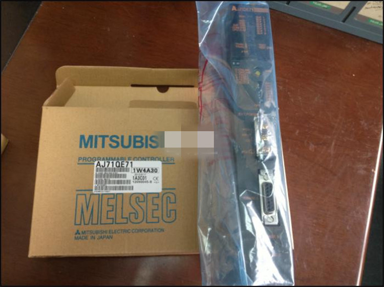
MITSUBISHI AJ71QE71 Manual And Instructions
AJ71QE71 datasheetPDF datasheet
AJ71QE71 HardwareUser's Manual
AJ71QE71 User's Manual
MITSUBISHI AJ71QE71 Product information and technical parameters:
Brand: MITSUBISHI
Name: Ethernet module
Model: AJ71QE71
Ethernet network module 10BASE5/10BASE2
Control layer /MELSECNET/10 (H) is the middle layer of the whole network system,
Control network which is convenient and high speed processing data transmission between PLC, CNC and other control equipment.
As MELSEC control network MELSECNET/10,
With its good real-time performance, simple network settings, no procedures of the network data sharing concept,
As well as the redundant circuit and so on, has obtained the very high market appraisal,
The number of devices to reach the highest in japan,
In the world is also one of the few.
And MELSECNET/H not only inherited the excellent characteristics of MELSECNET/10,
Also makes the network real-time better, more data capacity,
Further adapt to the needs of the market.
...More relevant models >>>>
AJ71QE71 datasheetPDF datasheet
AJ71QE71 HardwareUser's Manual
AJ71QE71 User's Manual
MITSUBISHI AJ71QE71 Product information and technical parameters:
Brand: MITSUBISHI
Name: Ethernet module
Model: AJ71QE71
Ethernet network module 10BASE5/10BASE2
Control layer /MELSECNET/10 (H) is the middle layer of the whole network system,
Control network which is convenient and high speed processing data transmission between PLC, CNC and other control equipment.
As MELSEC control network MELSECNET/10,
With its good real-time performance, simple network settings, no procedures of the network data sharing concept,
As well as the redundant circuit and so on, has obtained the very high market appraisal,
The number of devices to reach the highest in japan,
In the world is also one of the few.
And MELSECNET/H not only inherited the excellent characteristics of MELSECNET/10,
Also makes the network real-time better, more data capacity,
Further adapt to the needs of the market.
Input and output points: 2048 points.
Input / output data points: 8192 points.
Program capacity: 92k.
Basic command processing speed (LD command) S:0.15.
The length of time required to execute the instruction, the length of the user''s program, the type of instruction, and the speed of the CPU execution are very significant,
Generally, a scanning process, the fault diagnosis time,
Communication time, input sampling and output refresh time is less,
The execution time is accounted for the vast majority of AJ71QE71 AJ71QE71
The photoelectric coupler is composed of two luminous two extreme tubes and a photoelectric transistor.
Light emitting diode two: the input of a photo coupler and the change of electrical signal,
The light signal is generated by the light emitting diode, which is the same as the input signal AJ71QE71.
The working process of the input interface circuit: when the switch is closed, the diode light,
The transistor is then guided to the internal circuit and input signal under the irradiation of the light.
When the switch is off, the diode does not emit light, and the transistor is not on the way AJ71QE71. Internal circuit input signal.
It is through the input interface circuit to the external switch signal into PLC internal can accept the digital signal.
Photoelectric three levels: in the light of the light signal conduction, the degree of light signal and the intensity of the light signal.
The output signal has a linear relationship with the input signal in the linear operating region of the photoelectric coupler.
User program storage capacity: it is a measure of how much the user application can store the number of indicators.
Usually in words or K words as units. 16 bit binary number is a word,
Every 1024 words are 1K words. PLC to store instructions and data in words.
General logical operation instructions each account for 1 words. Timer / counter,
Shift instruction accounted for 2 words. Data operation instructions for 2~4.
Input and output points: 1024 points.
Input / output data points: 1024 points.
Program capacity: 14K.
Basic command processing speed (LD command) s:0.20.
Optical data communication line.
Each scanning process. Focus on the input signal sampling. Focus on the output signal to refresh.
Input refresh process. When the input port is closed,
Program in the implementation phase, the input end of a new state, the new state can not be read.
Only when the program is scanned, the new state is read.
A scan cycle is divided into the input sample, the program execution, the output refresh.
The contents of the component image register are changed with the change of the execution of the program.
The length of the scan cycle is determined by the three.
CPU the speed of executing instructions.
Time of instruction.
Instruction count.
Due to the adoption of centralized sampling.
Centralized output mode.
There exist input / output hysteresis phenomena, i.e., the input / output response delay.
User program storage capacity: iit is a measure of how much the user application can store the number of indicators AJ71QE71.
Usually in words or K words as units. 16 bit binary number is a word,
Every 1024 words are 1K words. PLC to store instructions and data in words.
General llogical operation instructions each account for 1 words AJ71QE71. Timer / counter,
Shift instruction accounted for 2 words. Data operation instructions for 2~4.
...More relevant models >>>>
 Last one:
  next one:
 Related download
