
Home
>> Products
>> MITSUBISHI
>> CC-Link module
>> Other CC-Link modules
>> NZ2AW1C2D2 Bridge module
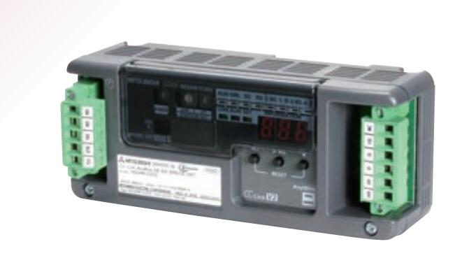
NZ2AW1C2D2 Bridge module
MITSUBISHI NZ2AW1C2D2 Manual And Instructions
NZ2AW1C2D2 datasheetPDF datasheet
MITSUBISHI NZ2AW1C2D2 Product information and technical parameters:
Brand: MITSUBISHI
Name: Bridge module
Model: NZ2AW1C2D2
The CC-Link-Anywire DB A20 bridge module.
Support Ver.2 CC-LINK.
...More relevant models >>>>
NZ2AW1C2D2 datasheetPDF datasheet
MITSUBISHI NZ2AW1C2D2 Product information and technical parameters:
Brand: MITSUBISHI
Name: Bridge module
Model: NZ2AW1C2D2
The CC-Link-Anywire DB A20 bridge module.
Support Ver.2 CC-LINK.
Output type: transistor output, source.
Output points: 16 points.
OFF leakage current: 0.1mA.
Output protection function.
Rated load voltage / current: DC12V/DC24V/0.1A.
External connection: 1 wire.
According to the external connection mode and the external equipment input and output specifications,
Choose from a rich product lineup NZ2AW1C2D2.
Finger protection through the upper part of the terminal,
The human body will not be exposed to live parts,
Therefore, the terminal station type remote I/O module can be directly mounted to the machine tool NZ2AW1C2D2 Output type: transistor output, source.
Output points: 16 points.
OFF leakage current: 0.1mA.
Output protection function.
Rated load voltage / current: DC24V/DC24V/0 NZ2AW1C2D2. 1A.
External connection: 3 wire.
Sensor connector type (E-CON type).
Using industry standard E-CON type.
Simple wiring through sensor connector.
When installing the module can choose to use the DIN guide rail or screw mounting.
3 wire sensor input. Screw, 2 piece type terminal
Temperature measuring resistor body input module.
Number of channels: 4 channels.
Number of stations: 1 stops NZ2AW1C2D2.
Station type: remote equipment station.
MITSUBISHI PLC online debugging.
On-line debugging is the process that will through the simulation debugging to further carry on the on-line unification to adjust.
On-line debugging process should be step by step,
From MITSUBISHI PLC only connected to the input device, and then connect the output device, and then connect to the actual load and so on and so on step by step.
If you do not meet the requirements, the hardware and procedures for adjustment.
Usually only need to modify the part of the program can be.
MITSUBISHI PLC hardware implementation
Hardware implementation is mainly for the control cabinet and other hardware design and field construction.
Design control cabinet and the operating table and other parts of tthe electrical wiring diagram and wiring diagram NZ2AW1C2D2.
Electrical interconnection diagram of each part of the design system.
According to the construction drawings of the site wiring, and carry out a detailed inspection.
Because the program deesign and hardware implementation can be carried out at the same time,
So the design cycle of the MITSUBISHI PLC control system can be greatly reduced NZ2AW1C2D2.
Output points: 16 points.
OFF leakage current: 0.1mA.
Output protection function.
Rated load voltage / current: DC12V/DC24V/0.1A.
External connection: 1 wire.
According to the external connection mode and the external equipment input and output specifications,
Choose from a rich product lineup NZ2AW1C2D2.
Finger protection through the upper part of the terminal,
The human body will not be exposed to live parts,
Therefore, the terminal station type remote I/O module can be directly mounted to the machine tool NZ2AW1C2D2 Output type: transistor output, source.
Output points: 16 points.
OFF leakage current: 0.1mA.
Output protection function.
Rated load voltage / current: DC24V/DC24V/0 NZ2AW1C2D2. 1A.
External connection: 3 wire.
Sensor connector type (E-CON type).
Using industry standard E-CON type.
Simple wiring through sensor connector.
When installing the module can choose to use the DIN guide rail or screw mounting.
3 wire sensor input. Screw, 2 piece type terminal
Temperature measuring resistor body input module.
Number of channels: 4 channels.
Number of stations: 1 stops NZ2AW1C2D2.
Station type: remote equipment station.
MITSUBISHI PLC online debugging.
On-line debugging is the process that will through the simulation debugging to further carry on the on-line unification to adjust.
On-line debugging process should be step by step,
From MITSUBISHI PLC only connected to the input device, and then connect the output device, and then connect to the actual load and so on and so on step by step.
If you do not meet the requirements, the hardware and procedures for adjustment.
Usually only need to modify the part of the program can be.
MITSUBISHI PLC hardware implementation
Hardware implementation is mainly for the control cabinet and other hardware design and field construction.
Design control cabinet and the operating table and other parts of tthe electrical wiring diagram and wiring diagram NZ2AW1C2D2.
Electrical interconnection diagram of each part of the design system.
According to the construction drawings of the site wiring, and carry out a detailed inspection.
Because the program deesign and hardware implementation can be carried out at the same time,
So the design cycle of the MITSUBISHI PLC control system can be greatly reduced NZ2AW1C2D2.
...More relevant models >>>>
 Last one:
  next one:
 Related download