Brand sort
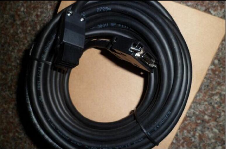
MITSUBISHI MITSUBISHI MR-J2HBUS15M Price
Brand:
MITSUBISHI
Country: JAPAN
Name: Enclosure
Model: MR-J2HBUS15M
Market price: U.S.$ 250.85
(The following are the market open price not sales price!)
(The following are the market open price not sales price!)
MITSUBISHI MR-J2HBUS15M
nothingRS-422 1 channel.
Transfer speed: 19.2/38.4bps.
AJ71C22-S1/A0J2-C214-S1 connection.
Input and output module connected with A0J2.
How to determine the input / output device of MITSUBISHI plc.
According to the control requirements of the system,
All input devices and output devices required for the determination of the system,
To determine the input / output device related to the MITSUBISHI PLC,
To determine the I/O PLC points MR-J2HBUS15M
Detailed analysis of the process and work characteristics of the controlled object,
To understand the coordination between the controlled object machine, electricity and liquid,
The control requirements of the controlled object for MITSUBISHI PLC control system are put forward,
Determine the control program, to develop a design task book. Power: 11kw.
Voltage: 400V.
There are 100% braking torque output in continuous regeneration, which can correspond to the continuous regeneration operation of the pipeline control.
There is no need to install the braking unit for each frequency converter, which can reduce the comprehensive space and reduce the comprehensive cost.
Renewable energy can be used for other frequency converter, excess energy back to the grid, to achieve energy saving. Protective film for 10.4 inch screen.
Scrub (frame: white), 5.
Applicable model: GT16. 8 point analog potentiometer function expansion board.Power: 11kw.
Purpose: high frequency braking resistor.
The use rate of the built-in regenerative brake of the transducer can be promoted.
When using the FR-ABR type brake resistor, the short circuit piece between the terminal PR-PX is removed. Does not remove the short circuit chip will lead to overheating of the brake resistor.
The utilization rate of the regenerative braking should be less than the allowable brake use rate in the above table.
With the operating frequency of the brake resistor to reach 300 degrees C or higher, it is necessary to take protective measures and cooling.
MYS type resistor can be used. But please pay attention to the allowable brake use rate.
Do not remove the terminal P/+ and P1 between the short circuit chip, in addition to connecting the DC reactor.
The installation of thermal relay, to avoid overheating and burn the braking resistor.
MR-J2HBUS15M Operation manual / Instructions / Catalog download link: /searchDownload.html?Search=MR-J2HBUS15M&select=5
...more relevant model market price >>>>
Related products
MITSUBISHI
Controller to amplifier bus cable
MR-J2HBUS5M-A
Cale length: 5.0M. Used in MR-J2S-700B
MITSUBISHI
Controller to amplifier bus cable
MR-J2HBUS1M-A
Cale length: 1.0M. Used in MR-J2S-700B
MITSUBISHI
Controller to amplifier bus cable
MR-J2HBUS05M-A
Cale length: 0.5M. Used in MR-J2S-700B
MITSUBISHI
Enclosure
MR-J2HBUS05M
Cale length: 0.5M.
Amplifier CC-Link in
Related download


 next one:
  Last one: