
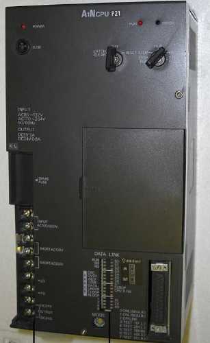
A1NCPUP21 CPU unit
MITSUBISHI A1NCPUP21 Manual And Instructions
A1NCPUP21 datasheetPDF datasheet
A1NCPUP21 Common InstructionsProgramming Manual
A1NCPUP21 User's Manual
A1NCPUP21 HardwareUser's Manual
A1NCPUP21 Dedicated InstructionsProgramming Manual
A1NCPUP21 FundamentalsProgramming Manual
MITSUBISHI A1NCPUP21 Product information and technical parameters:
Brand: MITSUBISHI
Name: CPU unit
Model: A1NCPUP21
Input and output points: 256 points.
Input / output data points: 256 points.
Program capacity: 6k.
Basic command processing speed (LD command) s:1.0.
Internal storage RAM memory capacity: 16k.
Optical data communication line function with power supply.
User program storage capacity: it is a measure of how much the user application can store the number of indicators.
Usually in words or K words as units. 16 bit binary number is a word,
Every 1024 words are 1K words. PLC to store instructions and data in words.
General logical operation instructions each account for 1 words. Timer / counter,
Shift instruction accounted for 2 words. Data operation instructions for 2~4.
Integral type: the PLC components are installed together or a few pieces of printed circuit board,
And together with the power supply installed in the casing to form a single overall called the host or the basic unit, small, ultra small PLC using this structure.
Modular: PLC is the basic components of a separate module.
Medium and large PLC used this way. Easy maintenance.
...More relevant models >>>>
A1NCPUP21 datasheetPDF datasheet
A1NCPUP21 Common InstructionsProgramming Manual
A1NCPUP21 User's Manual
A1NCPUP21 HardwareUser's Manual
A1NCPUP21 Dedicated InstructionsProgramming Manual
A1NCPUP21 FundamentalsProgramming Manual
MITSUBISHI A1NCPUP21 Product information and technical parameters:
Brand: MITSUBISHI
Name: CPU unit
Model: A1NCPUP21
Input and output points: 256 points.
Input / output data points: 256 points.
Program capacity: 6k.
Basic command processing speed (LD command) s:1.0.
Internal storage RAM memory capacity: 16k.
Optical data communication line function with power supply.
User program storage capacity: it is a measure of how much the user application can store the number of indicators.
Usually in words or K words as units. 16 bit binary number is a word,
Every 1024 words are 1K words. PLC to store instructions and data in words.
General logical operation instructions each account for 1 words. Timer / counter,
Shift instruction accounted for 2 words. Data operation instructions for 2~4.
Integral type: the PLC components are installed together or a few pieces of printed circuit board,
And together with the power supply installed in the casing to form a single overall called the host or the basic unit, small, ultra small PLC using this structure.
Modular: PLC is the basic components of a separate module.
Medium and large PLC used this way. Easy maintenance.
Input and output points: 512 points.
Input / output data points: 512 points.
Program capacity: 14K.
Basic command processing speed (LD command) s:1.0.
Optical data communication line function (GI cable).
Each scanning process. Focus on the input signal sampling. Focus on the output signal to refresh A1NCPUP21.
Input refresh process. When the input port is closed,
Program in the implementation phase, the input end of a new state, the new state can not be read A1NCPUP21
Only when the program is scanned, the new state is read.
A scan cycle is divided into the input sample, the program execution, the output refresh.
The contents of the component image register are changed with the change of the execution of the program A1NCPUP21.
The length of the scan cycle is determined by the three.
CPU the speed of executing instructions.
Time of instruction.
Instruction count.
Due to the adoption of centralized sampling.
Centralized output mode.
There exist input / output hysteresis phenomena, i.e., the input / output response delay.
User program storage capacity: it is a measure of how much the user application can store the number of indicators A1NCPUP21.
Usually in words or K words as units. 16 bit binary number is a word,
Every 1024 words are 1K words. PLC to store instructions and data in words.
General logical operation instructions each account for 1 words. Timer / counter,
Shift instruction accounted for 2 words. Data operation instructions for 2~4. SRAM capacity: 32K bytes.
AD59 (-S1) data storage.
On-line debugging is the process that will through the simulation debugging to further carry on the on-line unification to adjust.
On-line debugging process should be step by step,
From MITSUBISHI PLC only connected to the input device, and then connect the output device, and then connect to the actual load and so on and so on step by step.
If you do not meet the requirements, the hardware and procedures for adjustment.
Usually only need to modify the part of the program can beCable for unit load.
Length: 80mm.
Input / output unit standard equipment.
MITSUBISHI PLC pprogram simulation debugging
The basic idea of program simulation debugging is,
In order to facilitate the form of simulation to generate the actual state of the scene,
Create the necessary environmental conditions for the operation of thee program A1NCPUP21 A1NCPUP21.
Depending on the way the field signals are generated,
The simulation debugging has two forms of hardware simulation and software simulation.
...More relevant models >>>>
 Last one:
  next one:
 Related download
