
Home
>> Products
>> MITSUBISHI
>> Ans/QnAs series PLC
>> MELSECNET/10 module
>> A1SJ71QLP21 Network module
A1SJ71QLP21 Network module
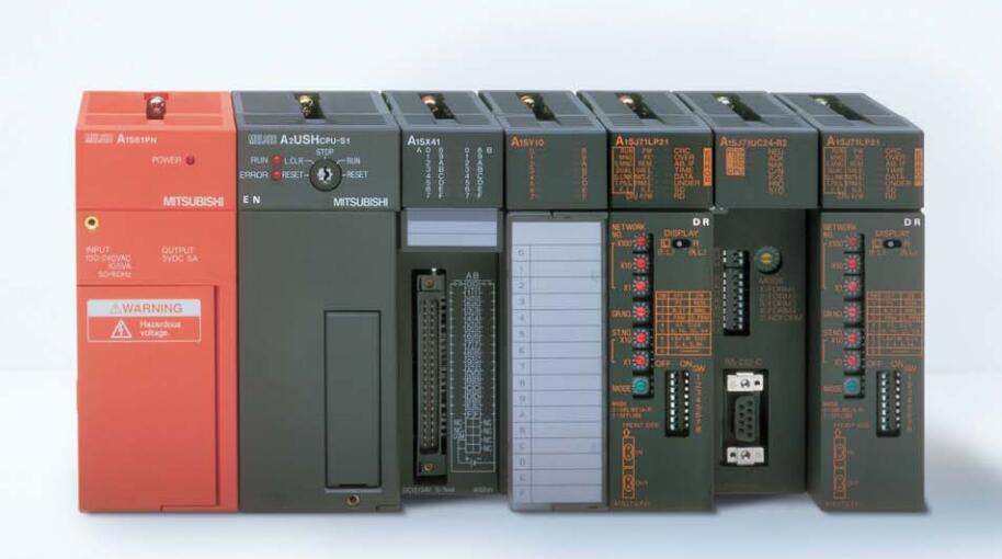
MITSUBISHI A1SJ71QLP21 Manual And Instructions
A1SJ71QLP21 datasheetPDF datasheet
A1SJ71QLP21 HardwareUser's Manual
A1SJ71QLP21 HardwareUser's Manual
MITSUBISHI A1SJ71QLP21 Product information and technical parameters:
Brand: MITSUBISHI
Name: Network module
Model: A1SJ71QLP21
SI/QSI/H-PCF/ wide H-PCF optical cable double loop PC (control station / common station) / remote I/O network (remote master station).
Switch volume control is designed to,
According to the current input combination of the switch quantity and the history of the input sequence,
So that PLC generates the corresponding switching output,
In order to make the system work in a certain order.
So, sometimes also known as the order control.
And sequential control is divided into manual, semi-automatic or automatic.
And the control principle is decentralized, centralized and hybrid control three.
The length of time required to execute the instruction, the length of the user''s program, the type of instruction, and the speed of the CPU execution are very significant,
Generally, a scanning process, the fault diagnosis time,
Communication time, input sampling and output refresh time is less,
The execution time is accounted for the vast majority of.
The response time of PLC is the interval between the time of the change of the external output signal of the PLC and the time of the change of the external output signal which is controlled by it,
Lag time, this is the time constant of the input circuit,
The time constant of the output circuit, the arrangement of the user statement and the use of the instruction,
The cycle scan mode of PLC and the way of PLC to refresh the I/O and so on.
This phenomenon is called the I/O delay time effect.
...More relevant models >>>>
A1SJ71QLP21 datasheetPDF datasheet
A1SJ71QLP21 HardwareUser's Manual
A1SJ71QLP21 HardwareUser's Manual
MITSUBISHI A1SJ71QLP21 Product information and technical parameters:
Brand: MITSUBISHI
Name: Network module
Model: A1SJ71QLP21
SI/QSI/H-PCF/ wide H-PCF optical cable double loop PC (control station / common station) / remote I/O network (remote master station).
Switch volume control is designed to,
According to the current input combination of the switch quantity and the history of the input sequence,
So that PLC generates the corresponding switching output,
In order to make the system work in a certain order.
So, sometimes also known as the order control.
And sequential control is divided into manual, semi-automatic or automatic.
And the control principle is decentralized, centralized and hybrid control three.
The length of time required to execute the instruction, the length of the user''s program, the type of instruction, and the speed of the CPU execution are very significant,
Generally, a scanning process, the fault diagnosis time,
Communication time, input sampling and output refresh time is less,
The execution time is accounted for the vast majority of.
The response time of PLC is the interval between the time of the change of the external output signal of the PLC and the time of the change of the external output signal which is controlled by it,
Lag time, this is the time constant of the input circuit,
The time constant of the output circuit, the arrangement of the user statement and the use of the instruction,
The cycle scan mode of PLC and the way of PLC to refresh the I/O and so on.
This phenomenon is called the I/O delay time effect.
SRAM memory card.
RAM capacity: 128KB. RS-232 1 channel.
RS-422/485 1 channel.
Transfer speed: 0.3-19.2kbps.
Input status and input information input from the input interface,
CPU will be stored in the working data memory or in the input image register.
And then combine the data and the program with CPU A1SJ71QLP21.
The result is stored in the output image register or the working data memory,
And then output to the output interface, control the external drive A1SJ71QLP21
Semiconductor circuit with memory function.
System program memory and user memory.
System program memory for storing system program,
Including management procedures, monitoring procedures, as well as the user program to do the compiler to compile the process of interpretation A1SJ71QLP21.
Read only memory. Manufacturers use, content can not be changed, power does not disappear. Input: AC100 ~ 120V/200 ~ 240V,
Output: 3A/DC24V 0.6A DC5V.
PLC programming has a wide range of applications, powerful, easy to use, has become one of the main devices of modern industrial automation,
In all areas of industrial production has been widely used,
Applications in other areas (such as civil and home automation) have also been rapidly developed A1SJ71QLP21.
It uses programmable memory,
An instruction used to perform logical operations, sequence control, timing, counting and arithmetic operations in its internal storage,
And through digital, analog input and output,
Control of various types of machinery or production processes. Programmable controller and related equipment,
Should be easy to make the industrial control system to form a whole, easy to expand the principle design of its functions.
As can be seen from the above definition, PLC is a program to change the control function of the industrial control computer,
In addition to the completion of a wide variety of control functions, as well as with other computer communications networking features. Input type: AC.
Input points: 16 points.
Input voltage: AC100-120V.
Input current: 6mA.
Connection mode: terminal row.
Common common point: 16.
The instruction list programming language is a programming language similar to assembly language mnemonic,
As well as assembly language by the operation code and the number of operations.
In the case of the computer for the PLC handheld programmer compile user program.
At the same time, the programming language of the instruction list corresponds to the ladder diagram programming language,
In PLC programming software can be converted to each other. Figure 3 is the instruction sheet corresponding to the ladder diagram of figure 2PLC.
The characteristics of instruction table programminng language is used to represent mnemonic operation function,
Easy to remember, easy to grasp;
In the handheld programmer on the keyboard using the mnemonic representation, easy to operate, can be programmed in computer;
There is a one-tto-one correspondence between the ladder diagram and the ladder diagram A1SJ71QLP21 A1SJ71QLP21. Its characteristics are basically consistent with the ladder diagram language.
...More relevant models >>>>
 Last one:
  next one:
 Related download