Home
>> Products
>> MITSUBISHI
>> Ans/QnAs series PLC
>> MELSECNET/10 module
>> A1SJ71QLP21GE Network module
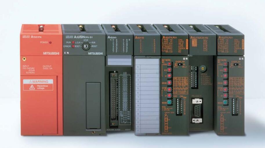
A1SJ71QLP21GE Network module
MITSUBISHI A1SJ71QLP21GE Manual And Instructions
A1SJ71QLP21GE datasheetPDF datasheet
A1SJ71QLP21GE HardwareUser's Manual
MITSUBISHI A1SJ71QLP21GE Product information and technical parameters:
Brand: MITSUBISHI
Name: Network module
Model: A1SJ71QLP21GE
...More relevant models >>>>
A1SJ71QLP21GE datasheetPDF datasheet
A1SJ71QLP21GE HardwareUser's Manual
MITSUBISHI A1SJ71QLP21GE Product information and technical parameters:
Brand: MITSUBISHI
Name: Network module
Model: A1SJ71QLP21GE
Type of input: DC leakage.
Input points: 16 points.
Input voltage: DC24.
Input current: 7mA.
Connection mode: terminal row.
Common common point: 16.
The instruction list programming language is a programming language similar to assembly language mnemonic,
As well as assembly language by the operation code and the number of operations A1SJ71QLP21GE.
In the case of the computer for the PLC handheld programmer compile user program A1SJ71QLP21GE
At the same time, the programming language of the instruction list corresponds to the ladder diagram programming language,
In PLC programming software can be converted to each other. Figure 3 is the instruction sheet corresponding to the ladder diagram of figure 2PLC.
The characteristics of instruction table programming language is used to represent mnemonic operation function,
Easy to remember, easy to grasp;
In the handheld programmer on the keyboard using the mnemonic representation, easy to operate, can be programmed in computer;
There is a one-to-one correspondence between the ladder diagram and the ladder diagram A1SJ71QLP21GE. Its characteristics are basically consistent with the ladder diagram language A1SJ71QLP21GE. Data format: RTU.
Data bits: 8.
A1SJ71UC24-R2-S2 and A1SJ71UC24-R4-S2 allow the Ans series PLC to be connected to the MODBUS network,
As the network from the station, and in accordance with the instructions of the main station of the CPU Ans user storage area for data reading / writing.
In addition to supporting the MODBUS protocol, these components also support the standard dedicated communication protocol for A1SJ71UC24 components.
This feature makes the main station of the data acquisition and control with more flexibility.
Support MODBUS slave station protocol.
Supports 1 to 21 function code.
Two transmission modes: RTU or ASCII. Program memory capacity: 8k.
Input / output points: maximum 256 points.
A scan cycle of PLC musst pass through three stages: input sampling, program execution and output refresh A1SJ71QLP21GE.
PLC in the input sampling phase: first of all, in order to scan the sequence of all existing input latches in the input terminal of the state or input data read,
And write it into the corresponding input status register,
Refresh the input, then close the input port, enter the program execution stage A1SJ71QLP21GE.
...More relevant models >>>>
Related download


 Last one:
  next one: