
Home
>> Products
>> MITSUBISHI
>> A/QnA series PLC
>> High function module
>> Other high function modules
>> AD57-S2 Display module
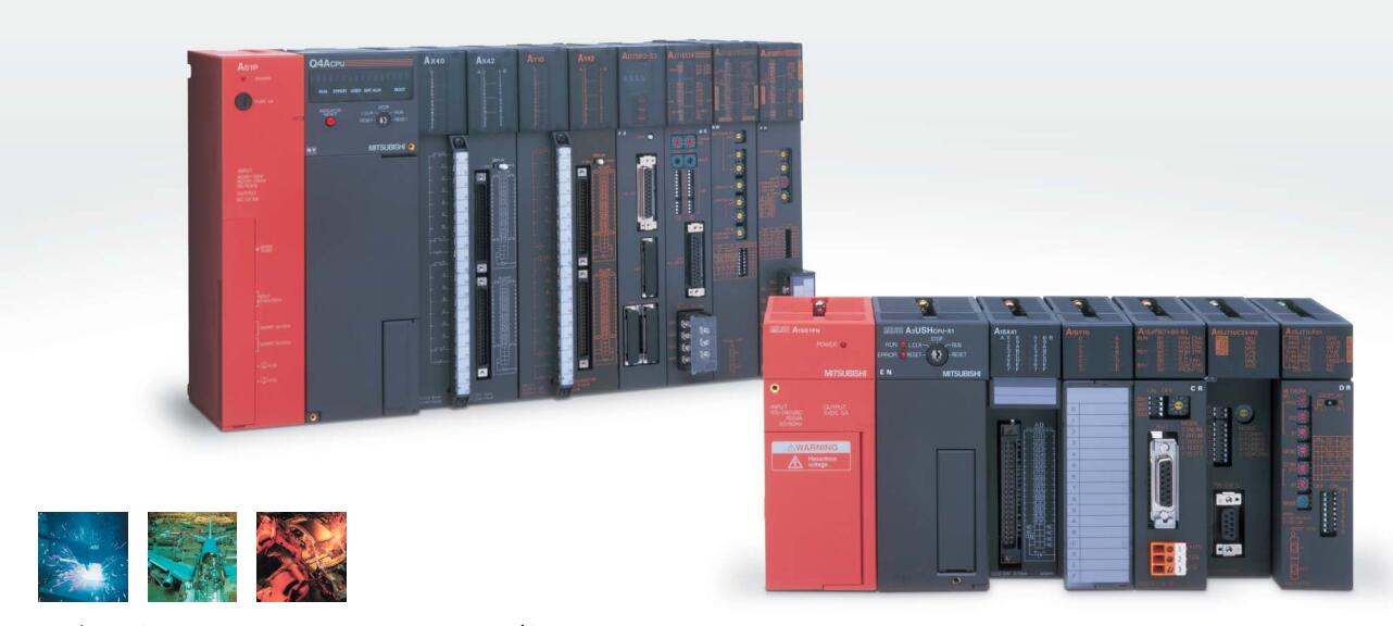
AD57-S2 Display module
MITSUBISHI AD57-S2 Manual And Instructions
AD57-S2 datasheetPDF datasheet
MITSUBISHI AD57-S2 Product information and technical parameters:
Brand: MITSUBISHI
Name: Display module
Model: AD57-S2
MITSUBISHI PLC hardware implementation
Hardware implementation is mainly for the control cabinet and other hardware design and field construction.
Design control cabinet and the operating table and other parts of the electrical wiring diagram and wiring diagram.
Electrical interconnection diagram of each part of the design system.
According to the construction drawings of the site wiring, and carry out a detailed inspection.
Because the program design and hardware implementation can be carried out at the same time,
So the design cycle of the MITSUBISHI PLC control system can be greatly reduced.
...More relevant models >>>>
AD57-S2 datasheetPDF datasheet
MITSUBISHI AD57-S2 Product information and technical parameters:
Brand: MITSUBISHI
Name: Display module
Model: AD57-S2
MITSUBISHI PLC hardware implementation
Hardware implementation is mainly for the control cabinet and other hardware design and field construction.
Design control cabinet and the operating table and other parts of the electrical wiring diagram and wiring diagram.
Electrical interconnection diagram of each part of the design system.
According to the construction drawings of the site wiring, and carry out a detailed inspection.
Because the program design and hardware implementation can be carried out at the same time,
So the design cycle of the MITSUBISHI PLC control system can be greatly reduced.
Multi axis positioning controller.
Coaxial data communication line function.
Program capacity: Max 60K step.
Input / output points: 1920 points.
The number of I/O thyristor DC motor control required tube DC motor speed control system is the main form of DC speed regulation,
The thyristor rectifier unit is used to supply power to the DC motor AD57-S2.
PLC control of the DC drive system, the input of the PLC in addition to the main signal outside the signal,
We need to consider the switching signal, the fault signal transmission device, brake signal and fan fault signal AD57-S2
The output of the PLC mainly consider the speed command signal positive 1~3 level, 1~3 level, allowing reverse switching signal and brake open signal etc AD57-S2. .
In general, a reversible DC drive system controlled by PLC is approximately 12 input points and 8 output points,
An irreversible DC drive system requires 9 inputs and 6 output points. 1 axes.
Control unit: pulse, mm, inch, degree.
Determine the location of the number of data: 600/1 axis.
36 pin connection SSCNET.
The working process of the input interface circuit: when the switch is closed, the diode light,
The transistor is then guided to the internal circuit and input signal under the irradiation of the light AD57-S2.
When the switch is off, the diode does not emit light, and the transistor is not on the way. Internal circuit input signal.
It is through the input interface circuit to the external switch signal into PLC internal can accept the digital signal.
PLC selection with the development of PLC technology, more and more types of PLC products,
Function is becoming more and more perfect, and its application is more and more extensive.
Different series of different models of PLC has different performance, applicable occasions also have different emphasis,
Price also has a greater difference. Therefore PLC selection,
Under the premise of meeting the control requirements,
Should consider the best performance to price ratio, a reasonable choice of PLC.
Input status and input information input from the input interface,
CPU will be stored in the working data memory or in the input image register.
And then combine the data and the program with CPU.
The result is stored in the output image register or the working data memory,
And then output to the output interface, control the exteernal drive AD57-S2.
MITSUBISHI PLC is the main product in the production of MITSUBISHI motor in Dalian.
It uses a kind of programmable memory for its internal storage procedures,
Execute logic operation, sequence control, timing, counting and arithhmetic operations, user oriented instruction,
And through digital or analog input / output control of various types of machinery or production process AD57-S2.
...More relevant models >>>>
 Last one:
  next one:
 Related download