
Home
>> Products
>> MITSUBISHI
>> A/QnA series PLC
>> High function module
>> Other high function modules
>> AD58 Display module
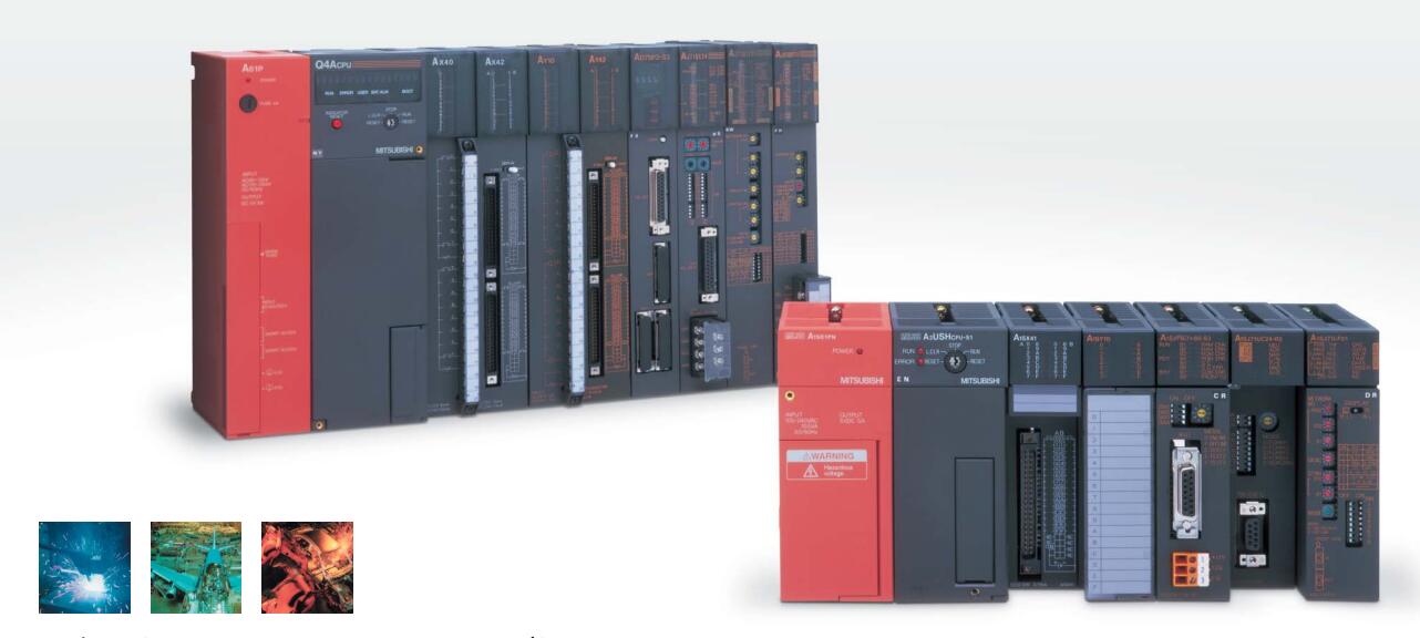
AD58 Display module
MITSUBISHI AD58 Manual And Instructions
AD58 datasheetPDF datasheet
AD58 User's Manual
AD58 User's Manual
MITSUBISHI AD58 Product information and technical parameters:
Brand: MITSUBISHI
Name: Display module
Model: AD58
MITSUBISHI PLC online debugging.
On-line debugging is the process that will through the simulation debugging to further carry on the on-line unification to adjust.
On-line debugging process should be step by step,
From MITSUBISHI PLC only connected to the input device, and then connect the output device, and then connect to the actual load and so on and so on step by step.
If you do not meet the requirements, the hardware and procedures for adjustment.
Usually only need to modify the part of the program can be.
...More relevant models >>>>
AD58 datasheetPDF datasheet
AD58 User's Manual
AD58 User's Manual
MITSUBISHI AD58 Product information and technical parameters:
Brand: MITSUBISHI
Name: Display module
Model: AD58
MITSUBISHI PLC online debugging.
On-line debugging is the process that will through the simulation debugging to further carry on the on-line unification to adjust.
On-line debugging process should be step by step,
From MITSUBISHI PLC only connected to the input device, and then connect the output device, and then connect to the actual load and so on and so on step by step.
If you do not meet the requirements, the hardware and procedures for adjustment.
Usually only need to modify the part of the program can be.
Fiber optic cable / twisted pair cable.
Single bus.
Remote I/O station.
According to the control requirements of the system, using the appropriate design method to design MITSUBISHI PLC program.
Procedures to meet the requirements of system control as the main line,
Write one by one to achieve the control function or the sub task of the program,
Gradually improve the functions specified by the system AD58 AD58
MITSUBISHI PLC initialization procedure. After MITSUBISHI PLC on power, the general need to do some of the initial operation,
In order to start making necessary preparations, to avoid the wrong operation of the system.
The main contents of the initialization program are: to some data area, counter and so on,
Data needed to restore some of the data area,
Set or reset some relays,
For some initial state display, etc AD58. . Input points: 32 points.
Input voltage and current: 3/7mA DC12/24V.
Input response time: 10ms.
16 point /1 a public side.
Output points: 24 points.
Output voltage: AC100 ~ 240V.
OFF leakage current: 3mA.
Output response time: 0.5Hz+1ms.
Output type: bidirectional thyristor output AD58.
36 point terminal station.
With short circuit protection.
With the surge absorber.
Control solenoid valve required I/O points by the action principle of the solenoid valve can be known,
A single coil solenoid valve with PLC control to 2 input and 1 output,
A double coil solenoid valve requires 3 inputs and 2 outputs,
A button needs an input; a light sensitive switch needs 4 or 2 inputs,
A signal lamp needs 1 output, band switch,
Several bands are required for several inputs,
In general, a variety of position switches are required to take up 2 input points.
MITSUBISHI PLC is the main product in the production of MITSUBISHI motor in Dalian.
It uses a kind of programmable memory for its internal storage procedures,
Execute logic operation, sequence control, timing, counting and arithmetic operations, user oriented instruction,
And through digital or analog input / output control of various types of machinery or production process.
The number of I/O thyristor DC motor control required tube DC motor speed control system is the main form of DC speed regulation,
The thyristor rectifier unit is used to supply power to the DC motor.
PLC control of the DC drive system, the input of the PLC in addition to the main signal outside the signal,
We need to consider the switching signal, the fault signal trransmission device, brake signal and fan fault signal AD58.
The output of the PLC mainly consider the speed command signal positive 1~3 level, 1~3 level, allowing reverse switching signal and brake open signal etc..
In general, a reversible DC drivee system controlled by PLC is approximately 12 input points and 8 output points,
An irreversible DC drive system requires 9 inputs and 6 output points AD58.
...More relevant models >>>>
 Last one:
  next one:
 Related download