
Home
>> Products
>> MITSUBISHI
>> CC-Link module
>> Remote I/O module
>> AJ65SBTB32-8DT DC input / transistor output module
AJ65SBTB32-8DT DC input / transistor output module
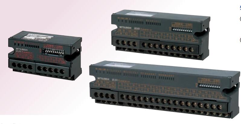
MITSUBISHI AJ65SBTB32-8DT Manual And Instructions
AJ65SBTB32-8DT datasheetPDF datasheet
MITSUBISHI AJ65SBTB32-8DT Product information and technical parameters:
Brand: MITSUBISHI
Name: DC input / transistor output module
Model: AJ65SBTB32-8DT
Input type: DC input, positive common end.
Input points: 4 points.
Enter the response time: 1.5ms the following.
Rated input voltage / current: DC24V/7mA.
Output form: transistor output, leakage type.
Output points: 4 points.
OFF leakage current: 0.25mA.
Output protection function.
Rated load voltage / current: DC24V/0.5A.
External connection: 3 line /2 line type.
According to the external connection mode and the external equipment input and output specifications,
Choose from a rich product lineup.
Finger protection through the upper part of the terminal,
The human body will not be exposed to live parts,
Therefore, the terminal station type remote I/O module can be directly mounted to the machine tool.
...More relevant models >>>>
AJ65SBTB32-8DT datasheetPDF datasheet
MITSUBISHI AJ65SBTB32-8DT Product information and technical parameters:
Brand: MITSUBISHI
Name: DC input / transistor output module
Model: AJ65SBTB32-8DT
Input type: DC input, positive common end.
Input points: 4 points.
Enter the response time: 1.5ms the following.
Rated input voltage / current: DC24V/7mA.
Output form: transistor output, leakage type.
Output points: 4 points.
OFF leakage current: 0.25mA.
Output protection function.
Rated load voltage / current: DC24V/0.5A.
External connection: 3 line /2 line type.
According to the external connection mode and the external equipment input and output specifications,
Choose from a rich product lineup.
Finger protection through the upper part of the terminal,
The human body will not be exposed to live parts,
Therefore, the terminal station type remote I/O module can be directly mounted to the machine tool.
Fast connector type.
Voltage output.
Number of channels: 8 channels.
Occupied the number of stations: Ver.1 mode occupied 3 stations, Ver.2 mode occupied 1 stations.
Station type: remote equipment station.
MITSUBISHI PLC hardware implementation
Hardware implementation is mainly for the control cabinet and other hardware design and field construction AJ65SBTB32-8DT.
Design control cabinet and the operating table and other parts of the electrical wiring diagram and wiring diagram AJ65SBTB32-8DT
Electrical interconnection diagram of each part of the design system.
According to the construction drawings of the site wiring, and carry out a detailed inspection.
Because the program design and hardware implementation can be carried out at the same time,
So the design cycle of the MITSUBISHI PLC control system can be greatly reduced AJ65SBTB32-8DT.
MITSUBISHI PLC online debugging.
On-line debugging is the process that will through the simulation debugging to further carry on the on-line unification to adjust.
On-line debugging process should be step by step,
From MITSUBISHI PLC only connected to the input device, and then connect the output device, and then connect to the actual load and so on and so on step by step AJ65SBTB32-8DT.
If you do not meet the requirements, the hardware and procedures for adjustment.
Usually only need to modify the part of the program can be. Fast connector type.
Voltage input.
Number of channels: 8 channels.
Occupied the number of stations: Ver.1 mode occupied 3 stations, Ver.2 mode occupied 1 stations.
Station type: remote equipment station.
MITSUBISHI PLC hardware implementation
Hardware implementation is mainly for the control cabinet and other hardware design and field construction.
Design control cabinet and the operating table and other parts of the electrical wiring diagram and wiring diagram.
Electrical interconnection diagram of each part of the design system.
According to the construction drawings of the site wiring, and carry out a detailed inspection.
Because the program design and hardware implementation can be carried out at the same time,
So the design cycle of the MITSUBISHI PLC control system can be greatly reduced.
MITSUBISHI PLC online debugging.
On-line debugging is the process that will through the simulation debugging to further carry on the on-line unification to adjust AJ65SBTB32-8DT.
On-line debugging process should be step by step,
From MITSUBISHI PLC only connected to the input device, and then connect the output device, and then connect to the actual load and so on and so on stepp by step AJ65SBTB32-8DT.
If you do not meet the requirements, the hardware and procedures for adjustment.
Usually only need to modify the part of the program can be.
...More relevant models >>>>
 Last one: MITSUBISHI Silicon controlled output module AJ65SBTB2N-16S
 next one: MITSUBISHI DC input / transistor output module AJ65SBTB32-8DT2
Related download