
Home
>> Products
>> MITSUBISHI
>> A/QnA series PLC
>> Network / serial communication module
>> AJ71QC24 Serial communication module
AJ71QC24 Serial communication module
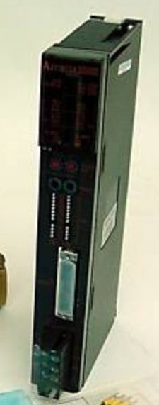
MITSUBISHI AJ71QC24 Manual And Instructions
AJ71QC24 datasheetPDF datasheet
AJ71QC24 HardwareUser's Manual
AJ71QC24 HardwareUser's Manual
AJ71QC24 GUIDEBOOK
AJ71QC24 Modem Function Additional VersionUser's Manual
MITSUBISHI AJ71QC24 Product information and technical parameters:
Brand: MITSUBISHI
Name: Serial communication module
Model: AJ71QC24
RS-232 1 channel, RS-422/485 1 channel.
Transfer speed: 0.3-19.2kbps.
Equipment layer / field bus CC-Link device layer is the PLC and other control devices and sensors and drive devices connected to the field network,
Network for the lowest layer of the whole network system.
Using CC-Link field bus connection, the number of wiring is greatly reduced,
Improve the maintainability of the system.
And, not just the amount of data ON/OFF and other switches,
Can also be connected to the ID system, bar code reader, inverter, man-machine interface and other intelligent devices,
From the completion of a variety of data communication, the management of the terminal production information can be realized,
On the centralized management of the state of the machine movement,
Make maintenance work efficiency also greatly improved.
Q series PLC in the use of CC-Link function better,
And easier to use.
...More relevant models >>>>
AJ71QC24 datasheetPDF datasheet
AJ71QC24 HardwareUser's Manual
AJ71QC24 HardwareUser's Manual
AJ71QC24 GUIDEBOOK
AJ71QC24 Modem Function Additional VersionUser's Manual
MITSUBISHI AJ71QC24 Product information and technical parameters:
Brand: MITSUBISHI
Name: Serial communication module
Model: AJ71QC24
RS-232 1 channel, RS-422/485 1 channel.
Transfer speed: 0.3-19.2kbps.
Equipment layer / field bus CC-Link device layer is the PLC and other control devices and sensors and drive devices connected to the field network,
Network for the lowest layer of the whole network system.
Using CC-Link field bus connection, the number of wiring is greatly reduced,
Improve the maintainability of the system.
And, not just the amount of data ON/OFF and other switches,
Can also be connected to the ID system, bar code reader, inverter, man-machine interface and other intelligent devices,
From the completion of a variety of data communication, the management of the terminal production information can be realized,
On the centralized management of the state of the machine movement,
Make maintenance work efficiency also greatly improved.
Q series PLC in the use of CC-Link function better,
And easier to use.
Output points: 16 points.
Voltage: DC24V/AC240V, 2A/1 point, 16A/ all points.
OFF leakage current: 0.1mA.
Output type: relay output.
Response time: 12ms.
All points of independence.
38 point terminal station.
With the surge absorber.
CE certification.
The number of I/O thyristor DC motor control required tube DC motor speed control system is the main form of DC speed regulation,
The thyristor rectifier unit is used to supply power to the DC motor AJ71QC24 AJ71QC24
PLC control of the DC drive system, the input of the PLC in addition to the main signal outside the signal,
We need to consider the switching signal, the fault signal transmission device, brake signal and fan fault signal.
The output of the PLC mainly consider the speed command signal positive 1~3 level, 1~3 level, allowing reverse switching signal and brake open signal etc AJ71QC24. .
In general, a reversible DC drive system controlled by PLC is approximately 12 input points and 8 output points,
An irreversible DC drive system requires 9 inputs and 6 output points.
MITSUBISHI PLC is the main product in the production of MITSUBISHI motor in Dalian AJ71QC24.
It uses a kind of programmable memory for its internal storage procedures,
Execute logic operation, sequence control, timing, counting and arithmetic operations, user oriented instruction,
And through digital or analog input / output control of various types of machinery or production process.
Control solenoid valve required I/O points by the action principle of the solenoid valve can be known,
A single coil solenoid valve with PLC control to 2 input and 1 output,
A double coil solenoid valve requires 3 inputs and 2 outputs,
A button needs an input; a light sensitive switch needs 4 or 2 inputs,
A signal lamp needs 1 output, band switch,
Several bands are required for several inputs,
In general, a variety of position switches are required to take up 2 input points. RS-232:1, RS-422/485:1.
Transmission speed: 0.3 ~ 19.2kpbs.
Computer connection function.
A3VCPU special.
Printer / peripheral device connection, BASIC language function.
How to choose MITSUBISHI PLC.
MITSUBISHI PLC options include the choice of MITSUBISHI PLC models, capacity, I/O module, power, etc..
MITSUBISHI PLC distribution I/O points and design MITSUBISHI PLC peripheral hardware circuit
Draw the I/O point of the PLC and the input / output device connection diagram or the corresponding table,
This part also can be carried out in second steps.
Dessign PLC peripheral hardware circuit AJ71QC24.
Draw the electrical wiring diagram of the other parts of the system,
Including the main circuit and the control circuit does not enter the PLC, etc..
The electrical schematic diagram of the system compoosed of I/O PLC connection diagram and PLC peripheral electrical circuit diagram AJ71QC24.
So far the system''s hardware electrical circuit has been determined.
...More relevant models >>>>
 Last one: MITSUBISHI Serial communication module AJ71QC24N-R4
 next one: MITSUBISHI Serial communication module AJ71QC24N-R2
Related download