
Home
>> Products
>> MITSUBISHI
>> A/QnA series PLC
>> Network / serial communication module
>> AJ71QC24N-R4 Serial communication module
AJ71QC24N-R4 Serial communication module
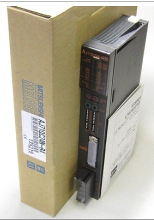
MITSUBISHI AJ71QC24N-R4 Manual And Instructions
AJ71QC24N-R4 datasheetPDF datasheet
AJ71QC24N-R4 HardwareUser's Manual
AJ71QC24N-R4 Modem Function Additional VersionUser's Manual
MITSUBISHI AJ71QC24N-R4 Product information and technical parameters:
Brand: MITSUBISHI
Name: Serial communication module
Model: AJ71QC24N-R4
RS-422 1 channel, RS-422/485 1 channel.
Transmission speed: 2 channel total is 115.2kbps.
Control layer /MELSECNET/10 (H) is the middle layer of the whole network system,
Control network which is convenient and high speed processing data transmission between PLC, CNC and other control equipment.
As MELSEC control network MELSECNET/10,
With its good real-time performance, simple network settings, no procedures of the network data sharing concept,
As well as the redundant circuit and so on, has obtained the very high market appraisal,
The number of devices to reach the highest in japan,
In the world is also one of the few.
And MELSECNET/H not only inherited the excellent characteristics of MELSECNET/10,
Also makes the network real-time better, more data capacity,
Further adapt to the needs of the market.
...More relevant models >>>>
AJ71QC24N-R4 datasheetPDF datasheet
AJ71QC24N-R4 HardwareUser's Manual
AJ71QC24N-R4 Modem Function Additional VersionUser's Manual
MITSUBISHI AJ71QC24N-R4 Product information and technical parameters:
Brand: MITSUBISHI
Name: Serial communication module
Model: AJ71QC24N-R4
RS-422 1 channel, RS-422/485 1 channel.
Transmission speed: 2 channel total is 115.2kbps.
Control layer /MELSECNET/10 (H) is the middle layer of the whole network system,
Control network which is convenient and high speed processing data transmission between PLC, CNC and other control equipment.
As MELSEC control network MELSECNET/10,
With its good real-time performance, simple network settings, no procedures of the network data sharing concept,
As well as the redundant circuit and so on, has obtained the very high market appraisal,
The number of devices to reach the highest in japan,
In the world is also one of the few.
And MELSECNET/H not only inherited the excellent characteristics of MELSECNET/10,
Also makes the network real-time better, more data capacity,
Further adapt to the needs of the market.
RS-422 1 channel.
Transfer speed: 38.4kbps.
Link points, 512 points.
The connection number: 8, 500m.
How to determine the input / output device of MITSUBISHI plc.
According to the control requirements of the system,
All input devices and output devices required for the determination of the system,
To determine the input / output device related to the MITSUBISHI PLC,
To determine the I/O PLC points AJ71QC24N-R4 AJ71QC24N-R4
Detailed analysis of the process and work characteristics of the controlled object,
To understand the coordination between the controlled object machine, electricity and liquid,
The control requirements of the controlled object for MITSUBISHI PLC control system are put forward,
Determine the control program, to develop a design task book AJ71QC24N-R4. Hardware implementation is mainly to control cabinet and other hardware design and field construction.
Design control cabinet and the operating table and other parts of the electrical wiring diagram and wiring diagram.
Electrical interconnection diagram of each part of the design system.
According to the construction drawings of the site wiring, and carry out a detailed inspection AJ71QC24N-R4.
Because the program design and hardware implementation can be carried out at the same time,
So the design cycle of the MITSUBISHI PLC control system can be greatly reduced. RS-232:1, RS-422/485:1.
Transmission speed: 0.3 ~ 19.2kpbs.
Computer connection function.
So far the system''s hardware electrical circuit has been determined.
Printer / peripheral device connection, BASIC language function.
How to choose MITSUBISHI PLC.
MITSUBISHI PLC options include the choice of MITSUBISHI PLC models, capacity, I/O module, power, etc..
MITSUBISHI PLC distribution I/O points and design MITSUBISHI PLC peripheral hardware circuit
Draw the I/O point of the PLC and the input / output device connection diagram or the corresponnding table,
This part also can be carried out in second steps AJ71QC24N-R4.
Design PLC peripheral hardware circuit.
Draw the electrical wiring diagram of the other parts of the system,
Including the main circuit and the control circuit does not entter the PLC, etc AJ71QC24N-R4. .
The electrical schematic diagram of the system composed of I/O PLC connection diagram and PLC peripheral electrical circuit diagram.
...More relevant models >>>>
 Last one: MITSUBISHI Serial communication module AJ71QC24N
 next one: MITSUBISHI Serial communication module AJ71QC24
Related download