
Home
>> Products
>> MITSUBISHI
>> Ans/QnAs series PLC
>> Analog module
>> A1S62DA Analog output module
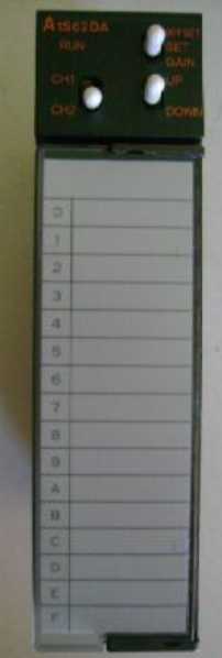
A1S62DA Analog output module
MITSUBISHI A1S62DA Manual And Instructions
A1S62DA datasheetPDF datasheet
A1S62DA HardwareUser's Manual
A1S62DA User's Manual
MITSUBISHI A1S62DA Product information and technical parameters:
Brand: MITSUBISHI
Name: Analog output module
Model: A1S62DA
2 channel analog output module.
As well as analog input modules, the A1S62DA analog output component is built into a microprocessor,
It can convert binary data into voltage or current signals,
Offset and gain are set and stored in a microprocessor,
It also includes other features as follows:
2 output channels.
High resolution digital input, plus or minus 12000.
Total accuracy plus or minus 1%.
...More relevant models >>>>
A1S62DA datasheetPDF datasheet
A1S62DA HardwareUser's Manual
A1S62DA User's Manual
MITSUBISHI A1S62DA Product information and technical parameters:
Brand: MITSUBISHI
Name: Analog output module
Model: A1S62DA
2 channel analog output module.
As well as analog input modules, the A1S62DA analog output component is built into a microprocessor,
It can convert binary data into voltage or current signals,
Offset and gain are set and stored in a microprocessor,
It also includes other features as follows:
2 output channels.
High resolution digital input, plus or minus 12000.
Total accuracy plus or minus 1%.
Input type: AC.
Input points: 16 points.
Input voltage: AC100-120V.
Input current: 6mA.
Connection mode: terminal row.
Common common point: 16.
The instruction list programming language is a programming language similar to assembly language mnemonic,
As well as assembly language by the operation code and the number of operations A1S62DA.
In the case of the computer for the PLC handheld programmer compile user program A1S62DA
At the same time, the programming language of the instruction list corresponds to the ladder diagram programming language,
In PLC programming software can be converted to each other. Figure 3 is the instruction sheet corresponding to the ladder diagram of figure 2PLC.
The characteristics of instruction table programming language is used to represent mnemonic operation function,
Easy to remember, easy to grasp;
In the handheld programmer on the keyboard using the mnemonic representation, easy to operate, can be programmed in computer;
There is a one-to-one correspondence between the ladder diagram and the ladder diagram A1S62DA. Its characteristics are basically consistent with the ladder diagram language A1S62DA. Input and output points: 512 points.
Input / output data points: 8192 points.
Program capacity: 28k.
Basic command processing speed (LD command) S:0.2.
PLC in the program execution stage: according to the order of the user program order to store the order of each instruction,
After the corresponding operation and processing, the result is written to the output status register,
The contents of the output status register are changed with the execution of the program.
Output refresh phase: when all instructions are executed,
The output status register is sent to the output latch in the output refresh stage,
And through a certain way (relay, transistor or transistor) output, drive the corresponding output equipment. 10Mbps transmission speed, the computer as the support of the flexible manufacturing system at the plant level, the requirements of more and more data flow,
High transmission speed can be guaranteed to increase the amount of transmitted data while maintaining the minimum time to transfer and receive data between programmable controllers.
The response time of PLC is the interval between the time of the change of the external output signal of the PLC and the time of the change of the external output signal which is controlled by it,
Lag time, this is the time constant of the input circuit,
The time constant of the output circuit, the arrangement of the user statement and the use of the instruction,
The cycle scan mode of PLC and the way of PLC to refresh the I/O and so on.
This phenomenon is called the I/O delay time effect.
Switch volume control is designed to,
According to the current inputt combination of the switch quantity and the history of the input sequence,
So that PLC generates the corresponding switching output,
In order to make the system work in a certain order A1S62DA.
So, sometimes also known as the order control.
And seqquential control is divided into manual, semi-automatic or automatic A1S62DA.
And the control principle is decentralized, centralized and hybrid control three.
...More relevant models >>>>
 Last one:
  next one:
 Related download