
Home
>> Products
>> MITSUBISHI
>> Ans/QnAs series PLC
>> Analog module
>> A1S63ADA Analog input / output module
A1S63ADA Analog input / output module
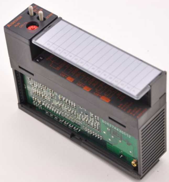
MITSUBISHI A1S63ADA Manual And Instructions
A1S63ADA datasheetPDF datasheet
A1S63ADA HardwareUser's Manual
A1S63ADA User's Manual
MITSUBISHI A1S63ADA Product information and technical parameters:
Brand: MITSUBISHI
Name: Analog input / output module
Model: A1S63ADA
Input channel number: 2.
Output channel number: 1.
Occupy I/O points: 32.
A1S63ADA analog input / output combination components can be analog / digital / digital / analog conversion,
The input and output signals can be voltage or current,
Offset and gain can be set and stored.
The length of time required to execute the instruction, the length of the user''s program, the type of instruction, and the speed of the CPU execution are very significant,
Generally, a scanning process, the fault diagnosis time,
Communication time, input sampling and output refresh time is less,
The execution time is accounted for the vast majority of.
The response time of PLC is the interval between the time of the change of the external output signal of the PLC and the time of the change of the external output signal which is controlled by it,
Lag time, this is the time constant of the input circuit,
The time constant of the output circuit, the arrangement of the user statement and the use of the instruction,
The cycle scan mode of PLC and the way of PLC to refresh the I/O and so on.
This phenomenon is called the I/O delay time effect.
...More relevant models >>>>
A1S63ADA datasheetPDF datasheet
A1S63ADA HardwareUser's Manual
A1S63ADA User's Manual
MITSUBISHI A1S63ADA Product information and technical parameters:
Brand: MITSUBISHI
Name: Analog input / output module
Model: A1S63ADA
Input channel number: 2.
Output channel number: 1.
Occupy I/O points: 32.
A1S63ADA analog input / output combination components can be analog / digital / digital / analog conversion,
The input and output signals can be voltage or current,
Offset and gain can be set and stored.
The length of time required to execute the instruction, the length of the user''s program, the type of instruction, and the speed of the CPU execution are very significant,
Generally, a scanning process, the fault diagnosis time,
Communication time, input sampling and output refresh time is less,
The execution time is accounted for the vast majority of.
The response time of PLC is the interval between the time of the change of the external output signal of the PLC and the time of the change of the external output signal which is controlled by it,
Lag time, this is the time constant of the input circuit,
The time constant of the output circuit, the arrangement of the user statement and the use of the instruction,
The cycle scan mode of PLC and the way of PLC to refresh the I/O and so on.
This phenomenon is called the I/O delay time effect.
Type of input: DC leakage.
Input points: 32 points.
Input voltage: DC24.
Input current: 7mA.
Connection mode: terminal row.
Common common point: 32.
Functional block diagram language is a kind of PLC programming language, which is similar to digital logic circuit.
The function module is used to represent the function of the module,
Different function modules have different functions A1S63ADA.
Functional module figure programming language features: functional block diagram programming language is characterized by a functional module for the unit,
Analysis and understanding of the control scheme is simple and easy: function module is to use graphical form of expression,
Intuitive, for a digital logic circuit based on the design of the staff is very easy to master the programming;
Control system with complex scale and complex control logic,
Because the function module diagram can clearly express the function relation, the programming debugging time is greatly reduced A1S63ADA A1S63ADA The most appropriate temperature regulation control (PID control) is possible,
In order to control the PID does not need to specify a special command A1S63ADA.
In addition, according to the automatic regulation function,
The automatic setting of PID number is possible.
The length of time required to execute the instruction, the length of the user''s program, the type of instruction, and the speed of the CPU execution are very significant,
Generally, a scanning process, the fault diagnosis time,
Communication time, input sampling and output refresh time is less,
The execution time is accounted for the vast majority of.
The response time of PLC is the interval between the time of the change of the external output signal of the PLC and the time of the change of the external output signal which is controlled by it,
Lag time, this is the time constant of the input circuit,
The time constant of the output circuit, the arrangement of the user statement and the usse of the instruction,
The cycle scan mode of PLC and the way of PLC to refresh the I/O and so on A1S63ADA A1S63ADA.
This phenomenon is called the I/O delay time effect.
...More relevant models >>>>
 Last one: MITSUBISHI Analog output module A1S68DAI
 next one: MITSUBISHI Analog input / output module A1S66ADA
Related download
